Electric motors are everywhere. They power household appliances, factory equipment, robotics, electric vehicles, pumps, fans, and many other machines we use every day. While motors come in many shapes and sizes, the basic idea is usually the same: they convert electrical energy into mechanical motion. This is achieved by the two key components of an electric motor: the electric motor stator and rotor. These two components work together to create rotation, generate torque, and transfer motion to the machine, or system, the motor is designed to drive.
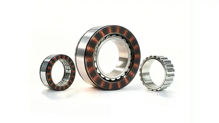
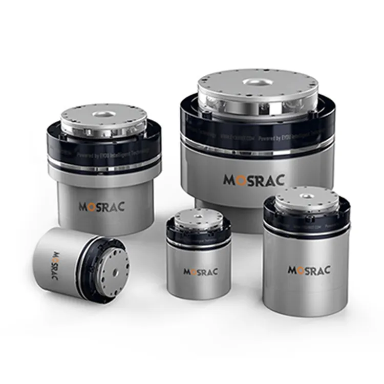
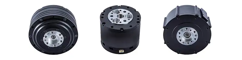
Key Components of Frameless torque motors - stator and rotor
In this article, we’ll explain what stators and rotors are, how they work together, how they differ, and why their design plays such an important role in motor performance. We’ll also look at the difference between internal rotor and external rotor motors.
What Is a Stator?
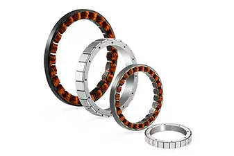
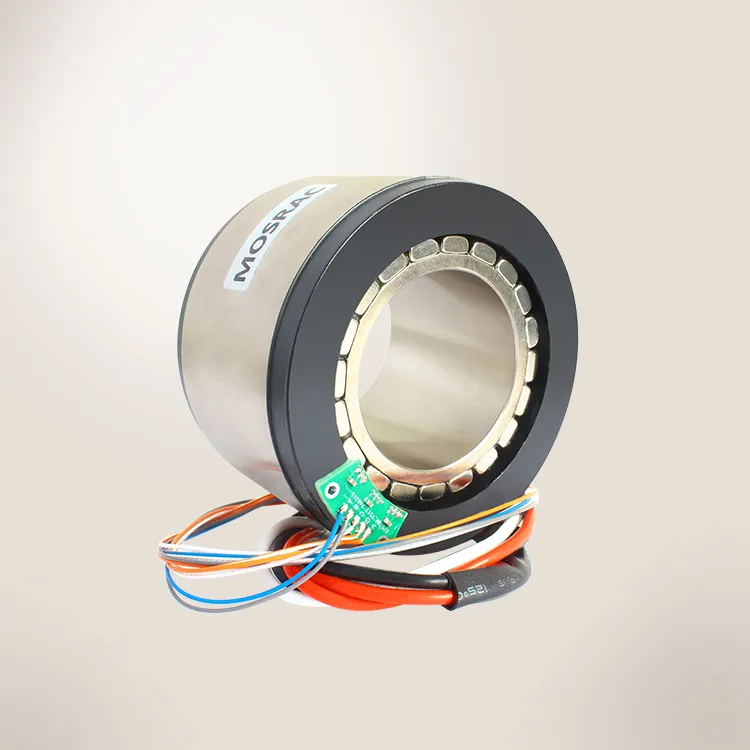
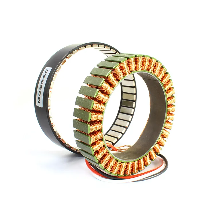
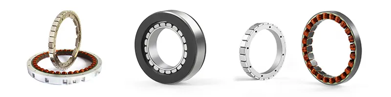
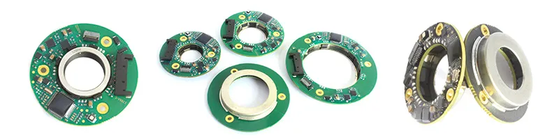
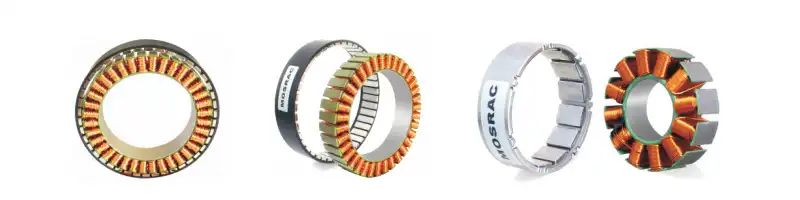
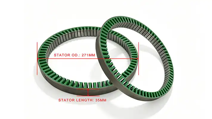
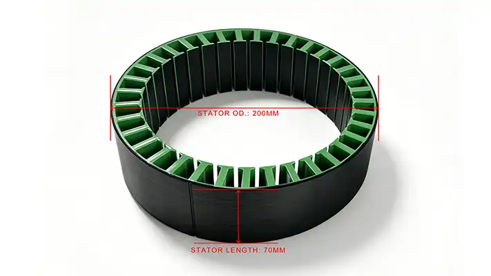
The stator, seen in Figure 1, is the stationary part of an electric motor. This means it does not rotate. Instead, it stays fixed in place and creates the magnetic field that helps drive the rotor.
In many electric motors, the stator is made from thin layers of laminated steel. These layers are stacked together to form the stator core. The laminations are important because they help reduce energy losses inside the motor, especially losses caused by unwanted electrical currents in the metal. By using thin insulated layers instead of one solid steel piece, the motor can operate more efficiently and generate less unnecessary heat.
The stator also contains copper windings, which are coils of copper wire placed into slots around the stator core. When electrical current flows through these windings, they create a magnetic field. This magnetic field is what interacts with the rotor and causes the motor to turn.
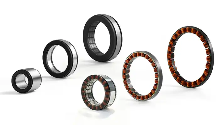
Figure 1. Stator Component in Electrical Motor.
What Is a Rotor?
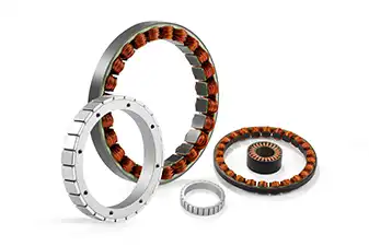
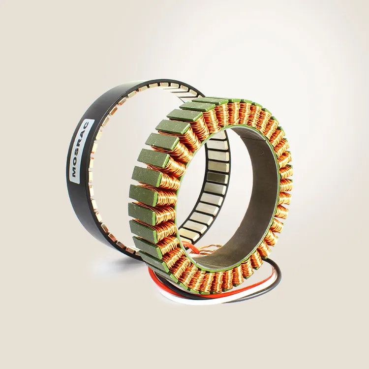
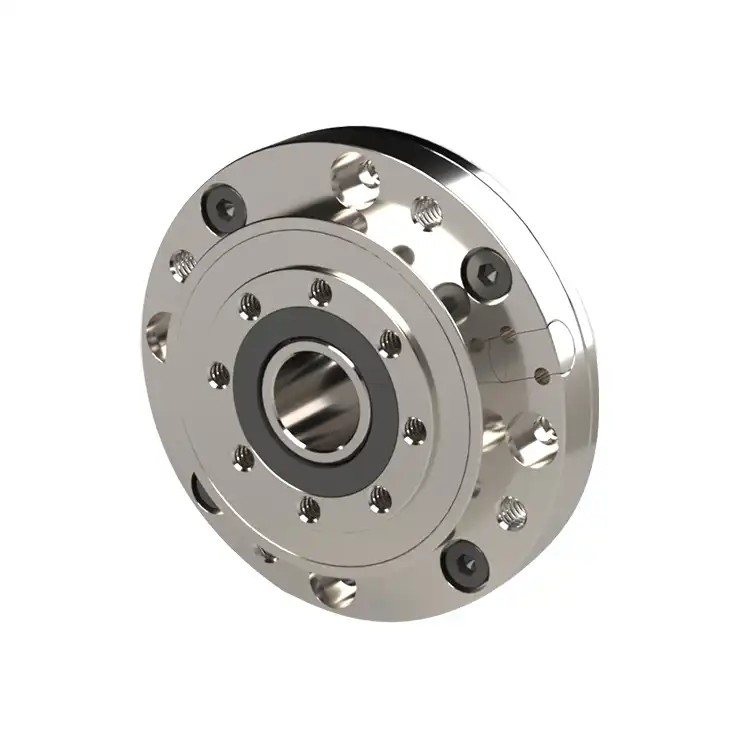
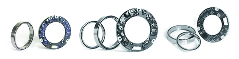
A rotor is the rotating part of an electric motor. It sits inside or around the stator, depending on the motor design, and turns when it interacts with the magnetic field produced by the stator.
The rotor is connected to the motor shaft. As the rotor spins, the shaft also rotates. This shaft then transfers mechanical motion to the load, such as a fan blade, wheel, pump, conveyor, robotic joint, or other moving part.
Different motor types use different rotor designs. Some rotors contain permanent magnets, which create their own magnetic field. Others use conductive bars or windings that respond to the magnetic field from the stator. In both cases, the goal is the same: to create a force that causes the rotor to turn. Figure 2 shows an image of a rotor.
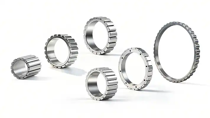
Figure 2. Rotor in Electric Motor.
How Stators and Rotors Work Together
A motor only works because the stator and rotor interact with each other. One creates the magnetic field, and the other responds to it. This interaction is what produces torque and rotation. The process starts when electrical current flows through the copper windings in the stator. These windings are arranged in a specific pattern so that the current creates a controlled magnetic field inside the motor.
As this magnetic field is created, it acts on the rotor. Depending on the motor type, the rotor may be pulled, pushed, or continuously guided by the changing magnetic field. This interaction creates a twisting force called torque. Torque is what causes the rotor to spin. Since the rotor is attached to the motor shaft, the shaft also rotates. The shaft then drives the connected load, turning electrical energy into useful mechanical motion.
The basic process steps can be summarized like this:
Electrical current flows through the stator windings.
The stator creates a magnetic field.
The magnetic field interacts with the rotor.
Torque is generated.
The rotor and shaft rotate.
The motor drives the connected load.
Stator vs Rotor: Key Differences
Although the stator and rotor work together, they have very different roles inside the motor.
Below is a rotor vs stator comparison table.
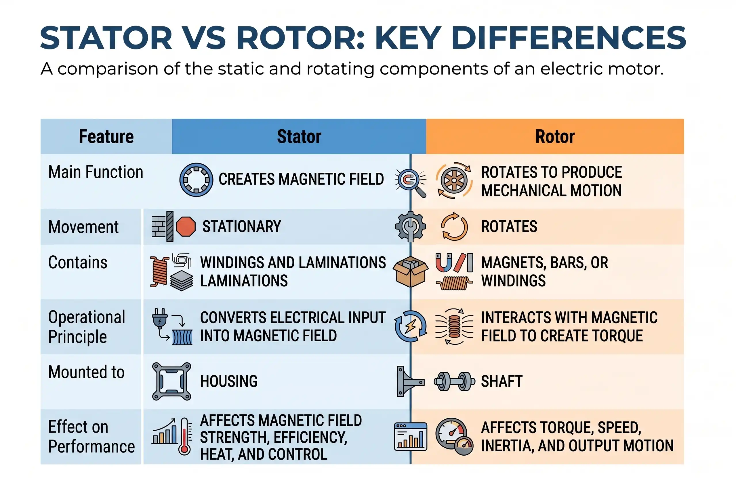
Table 1. Difference Between Stator and Rotor.
Internal Rotor vs External Rotor Motors
Electric motors can be designed in different ways depending on where the rotor is placed in relation to the stator. Two common configurations are internal rotor motors and external rotor motors. These are also often called inrunner and outrunner motors, respectively.
Internal Rotor (Inrunner)
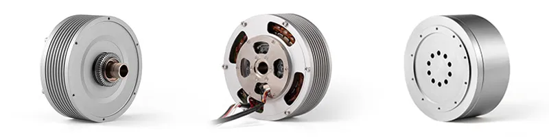
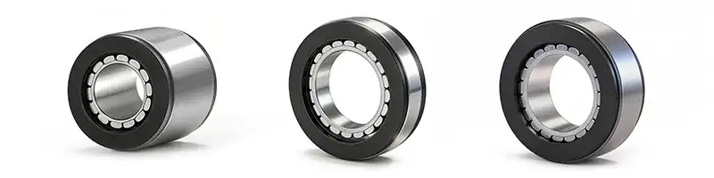
In an internal rotor motor, the rotor spins inside the stator. The stator surrounds the rotor, and the rotor is connected to the shaft at the center of the motor (see Figure 3).
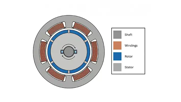
Figure 3. Schematic of an Internal Rotor Motor.
This design is commonly used in high-speed applications because the rotor is compact and has lower rotational inertia. Lower inertia means the motor can accelerate and decelerate more quickly, which is useful in applications that require fast response and precise motion control.
Internal rotor motors are often used in applications such as robotics, automation equipment, precision machinery, pumps, compressors, and high-speed motion systems.
Mosrac offers frameless internal rotor motor solutions with 17 frame diameters ranging from 16 to 200 mm, with multiple stack lengths for each diameter. These options support torque requirements of up to 100 Nm, making them suitable for a wide range of demanding motion applications.
External Rotor (Outrunner)
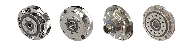
In an external rotor motor, the rotor surrounds the stator. Instead of spinning inside the stator, the rotor rotates around it. An outrunner motor is shown in Figure 4.
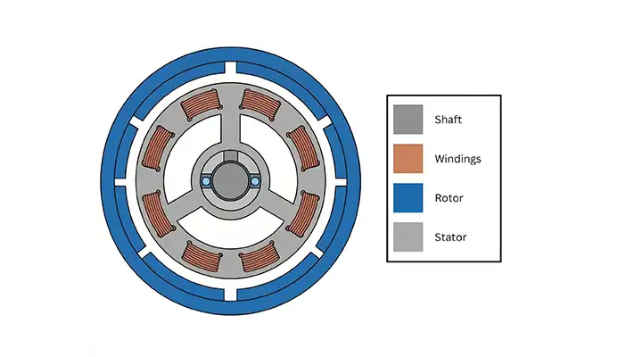
Figure 4. Schematic of an Outer Rotor Motor.
This design can provide higher torque density because the rotor has a larger diameter. A larger rotor diameter gives the motor more leverage, which can help produce more torque in a compact package. External rotor motors are often useful when the application requires strong torque at lower speeds.
Outrunner motors are commonly used in fans, blowers, drones, compact drive systems, and other applications where torque density and smooth rotation are important.
Mosrac offers frameless external rotor motor solutions with 11 frame diameters ranging from 15 to 109 mm, with multiple stack lengths for each diameter. These motors support torque requirements of up to 9.75 Nm, giving designers flexible options for compact, high-torque applications.
To learn more about the differences between internal and external rotor motors, you can read our in-depth article here.
Why Stator and Rotor Design Matters
The design of the stator and rotor has a direct effect on how a motor performs. Even when two motors look similar from the outside, differences in their internal design can lead to very different results. The table below shows the different design factors that should be taken into account.
From this table, we can see why motor design is not only about size or power rating. It is about matching the motor’s internal construction to the specific needs of the application.
Mosrac’s frameless motor options are available with multiple stack lengths and winding options. These designs can provide your machine with an ideal-fit frameless motor solution optimized for your application, whether you need high speed, compact torque, smooth motion, or a customized mechanical fit.
Tell us About Your Project
Every application has its own performance requirements. Some projects need high torque in a compact space. Others need fast acceleration, low noise, high efficiency, or a specific mechanical form factor. In many cases, a standard motor is close to what is needed, but not quite perfect for the final design.
Mosrac’s modified standard and completely custom versions of stator and rotor solutions are often provided to meet specific application demands. These options can help engineers match the motor more closely to the machine, system, or product they are developing.
Case Studies
Take a look to see how we create a better custom stator solution that meets the client's application demands.
Here are a few examples of our recent projects:
Are you considering integrating Mosrac’s solutions into your project? Talk to our experts to identify the motor solution best suited to your needs.
FAQs
What is the difference between a stator and rotor?
The stator is the stationary part of the motor, while the rotor is the rotating part. The stator creates the magnetic field, and the rotor interacts with that field to produce torque and rotation.
What does a stator do?
The stator produces the magnetic field that drives the rotor. It usually contains a laminated steel core and copper windings. When current flows through the windings, the stator generates the magnetic forces needed for motor operation.
What does a rotor do?
The rotor spins inside or around the stator. It reacts to the stator’s magnetic field and produces mechanical motion. Since the rotor is connected to the motor shaft, its rotation drives the connected load.
Which part of the motor rotates?
The rotor is the part of the motor that rotates. The stator remains fixed in place.
Why are laminations used?
Laminations are used to reduce energy losses inside the motor. Instead of using one solid piece of steel, the stator core is made from thin, insulated steel layers. This helps reduce unwanted currents, improve efficiency, and limit heat generation.
What is the air gap in a motor?
The small clearance between the rotor and stator.
Which component produces torque?
The rotor produces torque through interaction with the stator’s magnetic field.
Conclusion
The motor stator and motor rotor are the two main components that make electric motor operation possible. The stator stays still and creates the magnetic field, while the rotor spins in response to that field and transfers motion through the shaft.
Together, these parts determine how much torque the motor can produce, how efficiently it runs, how much heat it generates, how smooth it feels, and how reliable it will be over time. That is why stator and rotor design is so important in modern motor applications.
Explore Mosrac’s frameless inrunner and outrunner motors to find a stator and rotor solution that fits your project requirements.