Learn how a magnetic encoder works, its operating principles, accuracy factors, types, and key industrial applications in modern motion control systems.
Magnetic Encoder - Mosrac
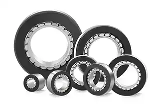
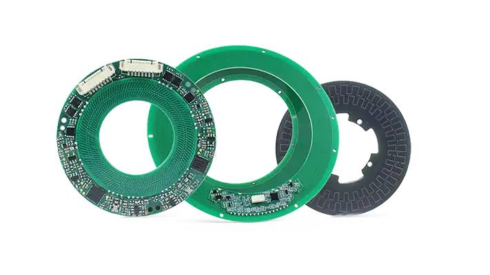
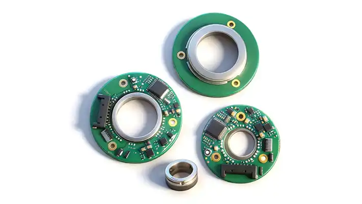
The magnetic encoder is a non-contact rotary or linear encoder that converts changes in a magnetic field into digital position signals.
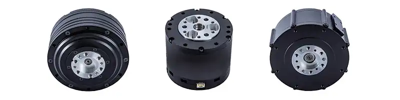
These encoders use magnetic sensing elements, such as Hall-effect or magnetoresistive sensors, to detect motion from a rotating shaft or moving scale without physical contact. This makes them especially effective for BLDC motors, servo systems, and robot joints operating in harsh or space-constrained environments.
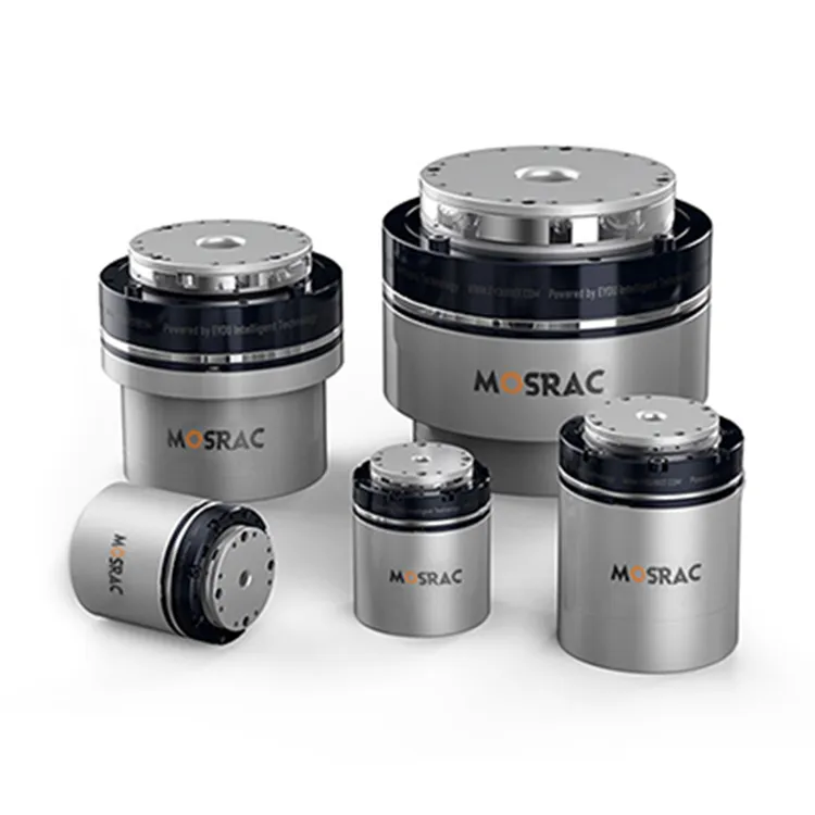
Mosrac specializes in high-precision magnetic encoder solutions designed for compact, high-performance motion control applications, including robotics, servo systems, and industrial automation.
Why Magnetic Encoders are Essential for Reliable Closed-Loop Control?
Reliable closed-loop control depends on accurate, repeatable position feedback under all operating conditions.
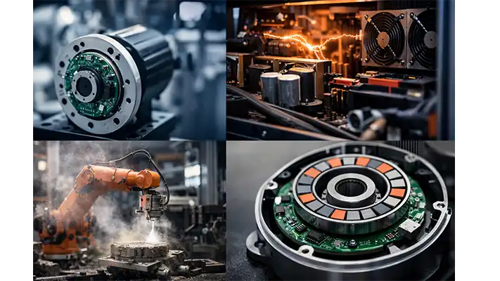
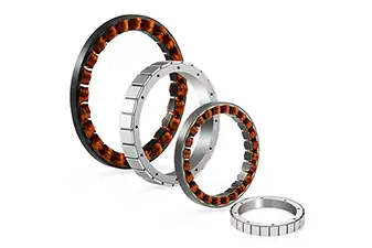
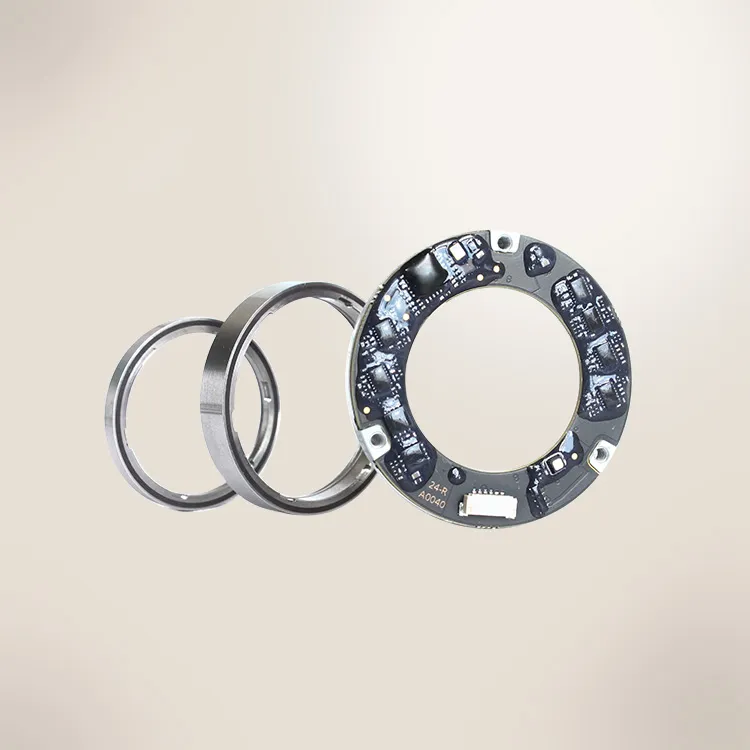
Magnetic Encoders in Industrial Settings
Let’s see why magnetic encoders are essential for reliable closed-loop control:
● Enabling Reliable Closed-Loop Control: Magnetic encoders provide accurate, real-time position feedback, enabling controllers to continuously correct motor output. This feedback loop is essential for servo motors, BLDC motors, and robotic joints. The precise speed and position control directly affect system stability and accuracy.
● EMI Resistance and Anti-Interference Performance: Because magnetic encoders do not depend on optical signals, they exhibit strong resistance to electromagnetic interference (EMI). This makes them highly reliable in environments with high switching currents, inverters, and power electronics commonly found in industrial motion control systems.
● Durability in Dust, Oil, and Vibration: Magnetic sensing is unaffected by contaminants that typically degrade optical systems. Magnetic encoders maintain stable signal quality in the presence of dust, oil, grease, and mechanical vibration, which is critical for factory automation, mobile robots, and heavy-duty machinery.
● Long Service Life and Low Maintenance: With no physical contact between sensing elements and the moving target, magnetic encoders experience minimal wear. This non-contact operation results in long service life, reduced maintenance requirements, and consistent performance over extended operating periods, even under continuous duty cycles.
Recommended Reading: What Is an Encoder? Everything You Need to Know
How Magnetic Encoders Work?
1. Core Working Principle
A magnetic encoder operates through a clear signal chain. Mechanical rotation or linear movement changes the orientation of a magnetic field. That field variation is detected by a magnetic sensor, converted into an electrical signal, and processed into digital position data.
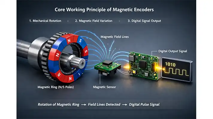
Core Working Principle of Magnetic Encoders
Because the process is non-contact, signal stability is maintained even at high speeds and under mechanical stress.
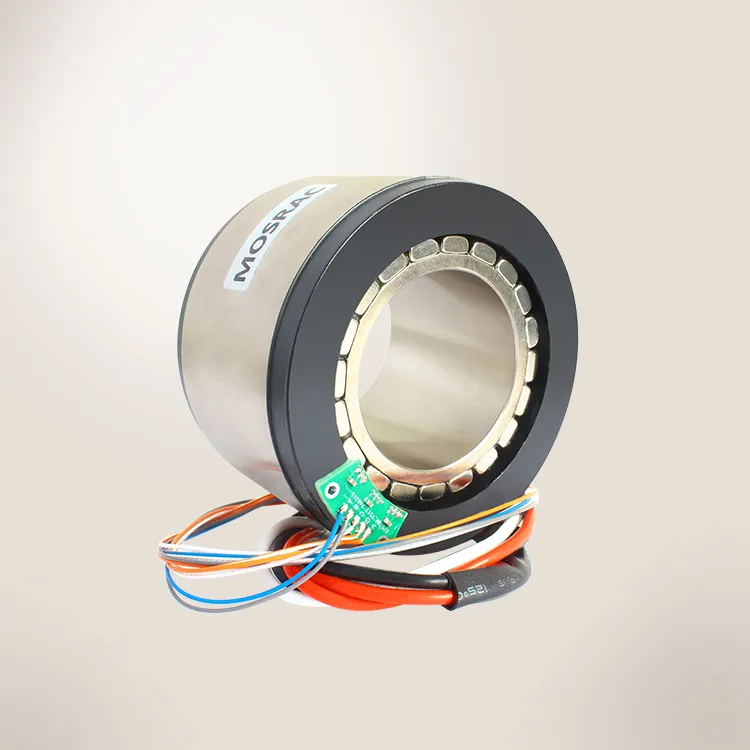
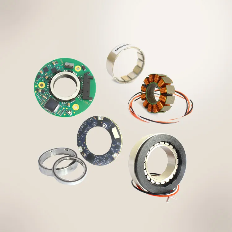
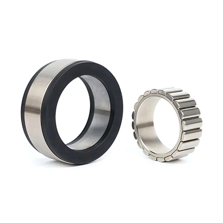
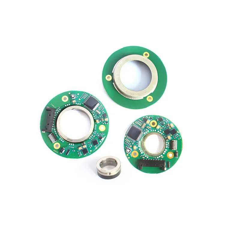
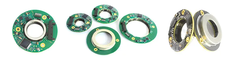
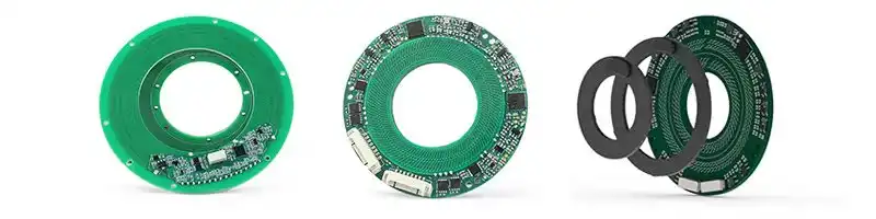
2. Key Components in a Magnetic Encoder System
The magnetic encoder typically consists of three core elements:
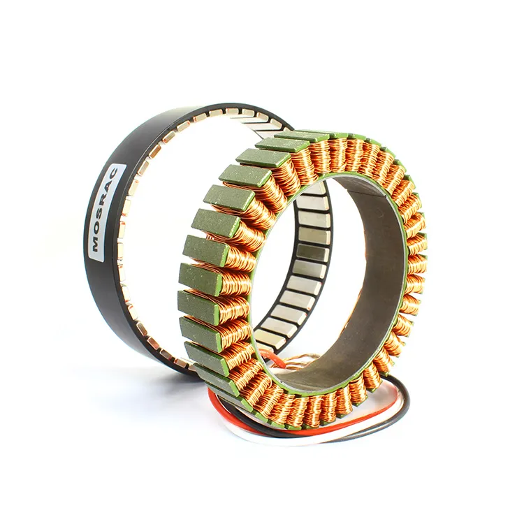
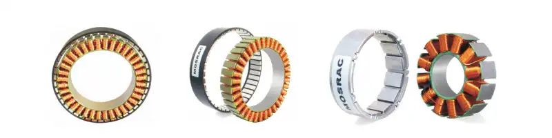
● Magnetic Ring or Pole Wheel: The permanently magnetized ring or wheel mounted on the rotating shaft or moving element. It contains defined north-south pole pairs that create a predictable magnetic field pattern.
● Sensor IC (Hall-Effect or Magnetoresistive): The solid-state sensor positioned near the magnetic ring. It detects changes in magnetic flux as the shaft rotates or moves.
● Signal-Processing Electronics: Electronics that amplify, filter, linearize, and convert the sensor output into precise digital position information.
3. Hall-Effect vs Magnetoresistive Sensing
Operating Physics
● Hall-Effect Sensors generate a voltage when exposed to a magnetic field perpendicular to the sensor surface.
● Magnetoresistive Sensors change electrical resistance based on the magnetic field direction and strength.
● Accuracy and Resolution Trade-Offs: Magnetoresistive sensing typically offers higher resolution and lower noise, while Hall-effect sensing provides cost-effective performance for many industrial applications.
● Temperature Stability Considerations: Magnetoresistive sensors generally offer better temperature stability, helping maintain accuracy across wide operating ranges.
4. Role of Pole Pairs, PPR, and Resolution
The number of magnetic pole pairs on the ring directly affects angular resolution. More pole pairs produce finer position increments.
● Pole Count vs Angular Resolution: Higher pole counts increase the pulses per revolution (PPR) and the effective resolution.
● Impact on Servo Motor Feedback Accuracy: Higher resolution improves commutation accuracy, torque smoothness, and positioning precision in servo motors and robotic joints.
Signal Processing and Data Calibration
Raw magnetic signals are not used directly. They are digitally processed and calibrated before output:
● Analog sensor data is filtered and linearized
● Position data is encoded into standard interfaces such as SSI, BiSS-C, or RS-485
● Error compensation corrects mechanical and magnetic imperfections
Magnetic Encodersat Mosrac undergo unique data-calibration shaping at the factory, where each unit is characterized against its specific magnetic field profile. This process enables consistent high-precision output, achieving angular accuracy typically in the ±0.01° to ±0.05° range, even in demanding motion-control systems.
For higher precision, the T-Series Magnetic Encoder offers 24-bit dual-axis resolution and ±0.01° accuracy in a compact form factor. Then there’s the PT Series Magnetic Encoder, with ultra-compact design, 24-bit absolute output and ±0.01° accuracy.
Recommended Reading: Single-Turn vs. Multi-Turn Encoders: The Lean Guide
Types of Magnetic Encoders
Magnetic encoders can be classified in several practical ways, depending on how motion is measured, how position data is output, how the encoder is installed, and where it is used.
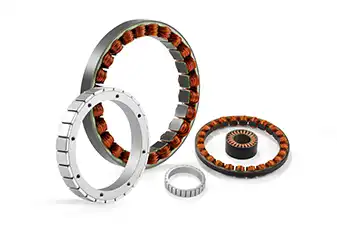
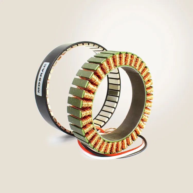
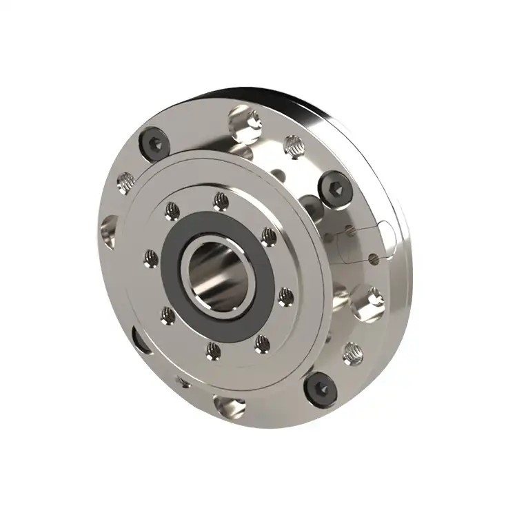
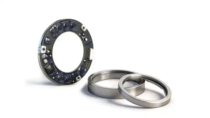
S-Series Magnetic Encoder - Mosrac
This classification helps engineers select the most suitable encoder for a specific motion-control application.
1. By Measurement Method
● Magnetic Rotary Encoders: Measure the angular position or rotation of a shaft. The magnetic ring with defined pole pairs rotates with the shaft, while a stationary sensor detects changes in the magnetic field. These encoders are used in servo motors, robotic joints, and industrial drives that require continuous rotational feedback.
● Magnetic Linear Encoders: Measure straight-line displacement instead of rotation. The magnetic scale moves linearly past the sensor, allowing accurate position tracking in applications such as linear actuators, CNC axes, and precision positioning systems.
2. By Output Type
● Absolute Magnetic Encoders: Provide a unique digital position value for every shaft or linear position. The true position is available immediately after power-up, making them ideal for robotics, safety-critical systems, and automated machinery.
● Incremental Magnetic Encoders: Generate pulses as motion occurs. Position is determined by counting these pulses relative to a reference point. They are commonly used for speed measurement, motion tracking, and cost-sensitive industrial applications.
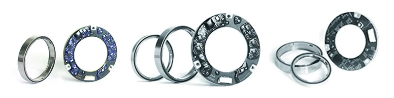
3. By Installation Style
● Shaft-Mounted Magnetic Encoders: Mechanically coupled to a motor or machine shaft. They are easy to install and commonly used in standard motor feedback and industrial automation systems.
● Hollow-Shaft Magnetic Encoders: Hollow-shaft designs slide directly over a shaft, reducing alignment errors and simplifying installation. They are preferred in compact motor assemblies and retrofit applications.
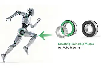
● Kit / Modular Magnetic Encoders: Separate the magnetic target and sensor into individual components. This design allows extremely compact integration, making it ideal for robot joints, frameless motors, and high-density mechatronic systems.
4. By Application
● Servo Motor Encoders: Used for precise position and speed feedback in closed-loop servo systems, ensuring smooth torque control and accurate motion.
● Robot Joint Encoders: Designed for high resolution and compact size, robot joint encoders support multi-axis synchronization and precise articulation in industrial and collaborative robots.
● Industrial Automation Encoders: Built for durability and EMI resistance, these encoders operate reliably in harsh factory environments involving dust, vibration, and electrical noise.
Recommended Reading: 14 Different Types of Encoders for Various Types of DC Motors
Absolute vs Incremental Magnetic Encoders
Absolute Magnetic Encoders
The absolute magnetic encoders provide a unique digital position value immediately at power-up. Each angular or linear position corresponds to a distinct digital code, so the controller always knows the exact position without any prior movement or homing sequence.
This behavior is critical in robotics, servo systems, and safety-critical applications, where unexpected motion after power loss is unacceptable. Absolute encoders enable faster system startup, improve operational safety, and simplify control logic in multi-axis systems. They are especially important in robot joints, direct-drive motors, and automated machinery that must resume operation from a known position.
Incremental Magnetic Encoders
Incremental magnetic encoders generate pulse-based feedback as motion occurs. Position is calculated by counting pulses relative to a reference point, while speed is derived from pulse frequency.
These encoders are cost-effective and efficient for applications focused on speed control, motion tracking, or relative positioning. Incremental magnetic encoders are commonly used in conveyors, pumps, fans, and industrial drives where absolute position recovery after power loss is not required.
Selection Guidance
Absolute Magnetic Encoders: Useful in robotics and collaborative robots, safety-related motion systems, applications requiring position recovery after power loss, and multi-axis systems with strict synchronization requirements.
Incremental Magnetic Encoders: Useful in speed and direction feedback, cost-sensitive industrial automation, systems with homing or reference routines, and non-safety-critical motion control.
For engineers evaluating both options, Mosrac offers a range of absolute and incremental magnetic encoder solutions designed for industrial reliability and precision.
Recommended Reading: Inductive Encoder: Working Principle, Types, Advantages & Industrial Applications
Performance Factors That Define Magnetic Encoder Accuracy
Resolution and PPR
Resolution, often expressed as pulses per revolution (PPR) or effective bits, defines how finely a magnetic encoder can distinguish position. Higher resolution enables smoother motor commutation, finer speed control, and more accurate positioning.
In servo and robotic systems, insufficient resolution can cause torque ripple, audible noise, and limit-cycle oscillations, while higher resolution improves trajectory tracking and repeatability.
Air Gap Tolerance and Mechanical Alignment
The air gap between the magnetic source and the sensor plays a critical role in signal quality. Magnetic encoders are generally more forgiving than optical encoders because they rely on magnetic flux rather than a clear optical path.
This tolerance allows them to maintain accuracy despite minor shaft runout, mechanical vibration, or assembly variation. Proper alignment still matters, but acceptable performance can be achieved without ultra-tight mechanical constraints.
Temperature Drift and Magnetic Stability
Temperature changes affect both the magnetic target and the sensor electronics. Drift can alter field strength and sensor response, leading to angle error.
To minimize this, high-quality magnetic encoders use temperature-compensated sensor ICs, stable magnetic materials, and factory calibration across operating ranges. Proper design maintains accuracy in applications exposed to wide ambient or self-heating conditions.
Signal Latency and Control Loop Impact
Latency, the delay between motion and reported position, directly impacts closed-loop control performance. In high-speed motion control, excessive latency reduces phase margin and limits control bandwidth.
The magnetic encoders, optimized for fast signal processing and high-speed interfaces, help maintain stable, responsive control loops. This is critical for high-dynamic servo systems, robotics, and precision automation.
Recommended Reading:Motor Encoders - Types, Features, Advantages, Applications, and Choosing the Right One
Common Industry Applications of Magnetic Encoders
● Robotics & Cobots: Magnetic encoders are widely used in robot joints and collaborative robots for precise angular position feedback. Their compact size, high resolution, and resistance to vibration make them ideal for multi-axis synchronization, smooth torque control, and backdrivable joints.
● Industrial Automation: In factory automation, magnetic encoders support conveyors, packaging machines, pick-and-place systems, and automated assembly lines. Their strong EMI resistance and tolerance to dust and oil ensure stable feedback in electrically noisy and mechanically demanding environments.
● Machine Tools: Magnetic encoders are used for axis position feedback and spindle monitoring in machine tools. They provide reliable performance under coolant exposure, metal debris, and vibration, while maintaining the resolution needed for repeatable machining and precision motion control.
● Printing Press: In printing systems, magnetic encoders enable accurate roller synchronization, web tension control, and registration alignment. Their immunity to ink mist, paper dust, and continuous operation conditions makes them well-suited for high-speed printing environments.
● Automotive: Magnetic encoders are applied in electric power steering, motor position sensing, throttle systems, and EV drivetrain components. Their ability to operate over wide temperature ranges and withstand shock and vibration meets stringent automotive reliability requirements.
● Aerospace: In aerospace systems, magnetic encoders support actuation systems, control surfaces, and positioning mechanisms. Their non-contact design and resistance to contamination help maintain accuracy in high-vibration and variable-temperature environments where maintenance access is limited.
● Gaming and Entertainment: Magnetic encoders are used in motion simulators, arcade systems, and haptic feedback platforms. They provide smooth, low-latency position feedback for responsive motion control, while their durability supports repetitive, high-cycle operation.
● Medical Equipment: Medical devices such as surgical robots, imaging systems, and precision actuators rely on magnetic encoders for accurate and quiet operation. Their compact form factor and stable performance support precise positioning and controlled motion in sensitive clinical environments.
● Harsh-Environment Motor Control: Magnetic encoders excel in outdoor, mobile, and heavy-duty motor control applications, including mining equipment, agricultural machinery, and mobile robots. Their tolerance to dust, oil, moisture, and vibration ensures reliable feedback where optical systems would degrade or fail.
Recommended Reading: Advantages of Magnetic Encoders in High‑Performance Automation
Choosing the Right Magnetic Encoder
Step 1 — Define Application Requirements
Start by defining the core motion parameters:
● Speed: Maximum rotational or linear velocity determines sensor bandwidth and interface speed.
● Torque and Dynamics: High-torque, high-acceleration systems benefit from higher resolution to reduce torque ripple.
● Resolution: Required angular or linear precision directly impacts positioning accuracy and motion smoothness, especially in servo and robotic systems.
These requirements dictate whether you need absolute position vs incremental feedback and what resolution level (e.g., 17-bit vs 24-bit) is appropriate.
Step 2 — Evaluate Environment
The environmental factors strongly influence encoder choice:
● Dust and Oil: Favor non-contact magnetic sensing to avoid signal degradation.
● EMI: High switching currents and drives require strong electromagnetic immunity.
● Temperature: Wide operating ranges demand stable magnetic materials and temperature-compensated electronics.
Magnetic encoders are often preferred when optical systems cannot maintain reliability.
Step 3 — Select Encoder Type
Choose the configuration that best fits the control and mechanical design:
● Absolute vs Incremental
Absolute encoders provide true position at power-up and are essential for robotics and safety-critical systems.
Incremental encoders are suitable for speed and relative-motion tracking when homing is acceptable.
● Shaft vs Kit (Modular)
Shaft-mounted designs simplify installation in conventional motors.
Kit encoders separate the magnetic target and sensor, enabling compact integration in high-density assemblies and robotic joints.
Step 4 — Match Interface & Output
Interface selection must align with the control architecture:
● SSI and BiSS-C for deterministic, high-speed industrial communication
● SPI for compact, embedded control systems
Low latency and signal integrity are critical for high-performance closed-loop control.
Step 5 — Consult Mosrac for Optimization
Final optimization often requires more than selecting a catalog encoder. Mosrac supports custom encoder-to-motor matching, ensuring mechanical compatibility, optimal air gap control, and calibrated signal performance.
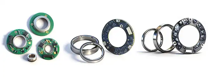
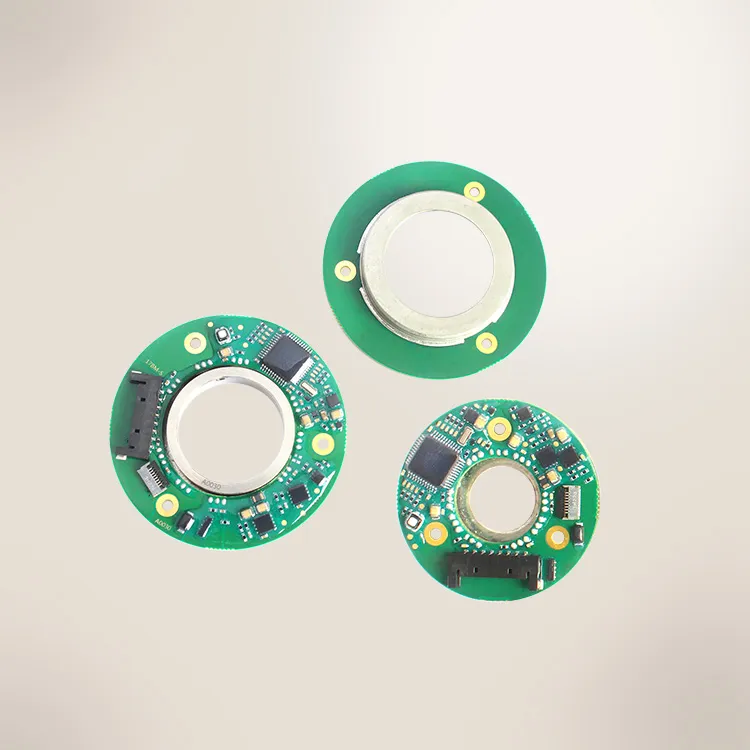
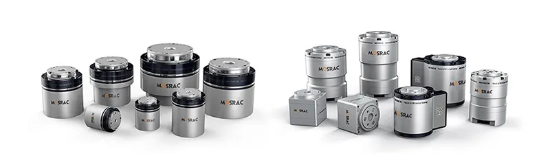
S-Series, T-Series, PT-Series - Magnetic Encoders by Mosrac
Mosrac offers:
S-Series Magnetic Encoders, an ultra-thin absolute magnetic encoder family offering high resolution (up to 17-bit) and ±0.05° accuracy, multiple output formats, and strong EMI tolerance in a hollow, compact package.
Standard Type:
| Size | Rotor ID | Stator OD | Stator shield OD | Overall thickness |
| S-8-36 | 8 | 36 | 20 | 7 |
| S-10-36 | 10 | 36 | 20 | 7 |
| S-12-40 | 12 | 40 | 25 | 7 |
| S-13-40 | 13 | 40 | 25 | 7 |
| S-15-40 | 15 | 40 | 25 | 7 |
| S-6-45 | 6 | 45 | 30 | 7 |
| S-8-45 | 8 | 45 | 30 | 7 |
| S-10-45 | 10 | 45 | 30 | 7 |
| S-15-45 | 15 | 45 | 30 | 7 |
| S-18-45 | 18 | 45 | 30 | 7 |
| S-20-45 | 20 | 45 | 30 | 7 |
| S-23-50 | 23 | 50 | 35 | 7 |
| S-25-50 | 25 | 50 | 35 | 7 |
| S-28-55 | 28 | 55 | 40 | 7 |
| S-30-55 | 30 | 55 | 40 | 7 |
| S-33-60 | 33 | 60 | 45 | 7 |
| S-35-60 | 35 | 60 | 45 | 7 |
| S-38-65 | 38 | 65 | 50 | 7 |
| S-40-65 | 40 | 65 | 50 | 7 |
| S-43-70 | 43 | 70 | 55 | 7 |
| S-45-70 | 45 | 70 | 55 | 7 |
| S-48-75 | 48 | 75 | 60 | 7 |
| S-50-75 | 50 | 75 | 60 | 7 |
| S-53-80 | 53 | 80 | 65 | 7 |
| S-55-80 | 55 | 80 | 65 | 7 |
Compact Type:
| Size | Rotor ID | Stator OD | Stator shield OD | Overall thickness |
| S-8-27 | 8 | 27 | 20 | 7 |
| S-10-27 | 10 | 27 | 20 | 7 |
| S-12-32 | 12 | 32 | 25 | 7 |
| S-13-32 | 13 | 32 | 25 | 7 |
| S-15-32 | 15 | 32 | 25 | 7 |
| S-18-37 | 18 | 37 | 30 | 7 |
| S-20-37 | 20 | 37 | 30 | 7 |
| S-23-42 | 23 | 42 | 35 | 7 |
| S-25-42 | 25 | 42 | 35 | 7 |
| S-28-47 | 28 | 47 | 40 | 7 |
| S-30-47 | 30 | 47 | 40 | 7 |
| S-33-52 | 33 | 52 | 45 | 7 |
| S-35-52 | 35 | 52 | 45 | 7 |
| S-38-57 | 38 | 57 | 50 | 7 |
| S-40-57 | 40 | 57 | 50 | 7 |
| S-43-62 | 43 | 62 | 55 | 7 |
| S-45-62 | 45 | 62 | 55 | 7 |
| S-48-67 | 48 | 67 | 60 | 7 |
| S-50-67 | 50 | 67 | 60 | 7 |
T-Series Magnetic Dual Encoders integrate dual feedback channels, enabling simultaneous position and commutation or redundancy-based designs. This configuration is valuable in applications that require enhanced reliability, functional safety concepts, or optimized motor control performance.
| Model | Inner Rotor ID | Outer Stator ID | Stator ID |
| T-10-15-25 | 9 | 14 | 25 |
| T-15-20-30 | 14 | 19 | 30 |
| T-20-25-35 | 19 | 24 | 35 |
| T-25-30-40 | 24 | 29 | 40 |
| T-30-35-45 | 29 | 34 | 45 |
PT-Series Magnetic Encoders focus on magnetic sensing with flexible integration, targeting industrial automation and motion systems. Its design balances accuracy, durability, and ease of installation, making it suitable for a wide range of automation equipment and motor-driven systems.
| Types | Rotor style | Stator OD | Overall thickness |
| PT-10-20 | Thread | 20 | 6.7 |
| PT-10B-20 | Bonding | 20 | 6.7 |
| PT-10-20H | Thread | 20 | 6.7 |
| PT-10B-20H | Bonding | 20 | 6.7 |
| PT-13-25 | Thread | 25 | 6.7 |
| PT-13-25H | Thread | 25 | 6.7 |
| PT-14-25 | Thread | 25 | 6.7 |
| PT-14-25H | Thread | 25 | 6.7 |
| PT-15-25 | Thread | 25 | 6.7 |
| PT-15B-25 | Bonding | 25 | 6.7 |
| PT-15-25H | Thread | 25 | 6.7 |
| PT-15B-25H | Bonding | 25 | 6.7 |
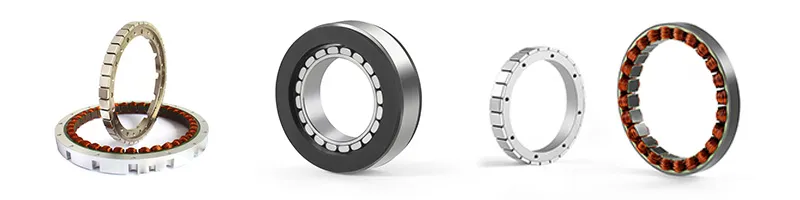
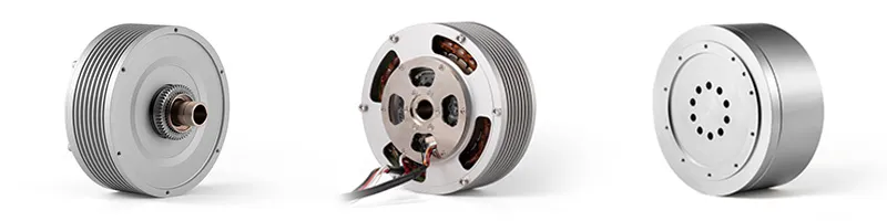
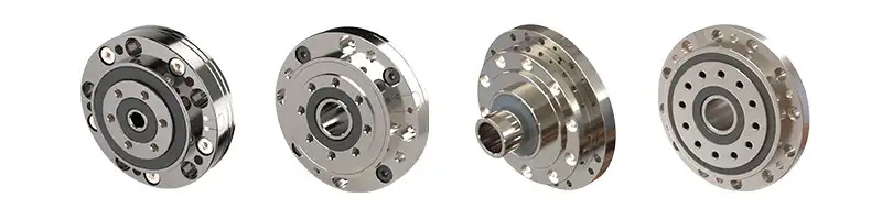
Integrated System Compatibility
Both variants are designed for seamless compatibility with frameless motors and torque motors. This supports integrated motor-encoder architectures that reduce system size, improve stiffness, and enhance dynamic response.
For application-specific encoder selection, mechanical integration guidance, and optimized motor-encoder solutions, our engineering team at Mosrac can recommend the most suitable magnetic encoder configuration - or design a custom solution for your applications.
Conclusion
Magnetic encoders provide accurate, non-contact position feedback for modern motion control systems. They offer strong EMI resistance, reliable performance in dust and oil, and long service life. Their compact design makes them ideal for robotics, servo motors, and harsh industrial environments.
Mosrac plays a key role in precision magnetic encoder engineering by delivering high-resolution, factory-calibrated solutions designed for real-world industrial demands. Explore the magnetic encoder portfolio or request a custom-engineered solution to ensure reliable, long-term motion feedback for your next application.
Frequently Asked Questions (FAQs)
1. What are magnetic encoders used for?
A. Magnetic encoders are used for position, speed, and angle feedback in motion control systems. The common applications include servo motors, robotics, industrial automation, AGVs, and equipment operating in dusty, oily, or high-vibration environments.
2. How do magnetic encoders work?
A. Magnetic encoders detect changes in a magnetic field generated by a rotating or moving target. Sensors convert these field variations into electrical signals, which are then processed to produce precise digital position data.
3. How many pole pairs should a magnetic encoder have?
A. The required number of pole pairs depends on resolution needs. Higher pole counts increase angular resolution and improve commutation accuracy, but must match sensor capability and mechanical constraints for optimal performance.
4. What causes angle error in magnetic encoders?
A. Angle error can result from magnetic field distortion, air-gap variation, mechanical misalignment, temperature drift, or insufficient calibration. High-quality encoders reduce these errors through sensor compensation and factory calibration.
5. When should I choose a hollow-shaft magnetic encoder?
A. The hollow-shaft magnetic encoder is ideal when easy installation, reduced alignment error, and compact integration are required. It is commonly used in servo motors, retrofit applications, and tight mechanical assemblies, including solutions offered by Mosrac.