Learn what an inductive encoder is, how it works, major advantages, and why inductive encoders are ideal for robotics and harsh industrial environments!
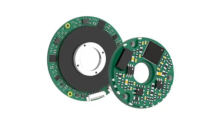
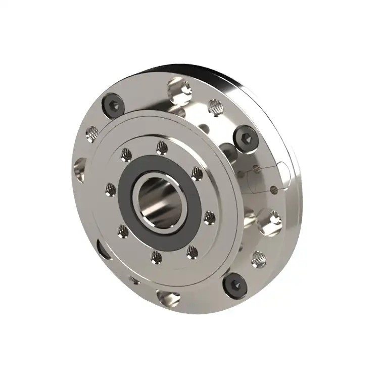
Inductive Encoder
What Is an Inductive Encoder?
The inductive encoder is a non-contact position sensor that uses electromagnetic induction to convert rotary or linear motion into reliable electrical feedback signals.
These encoders are preferred for applications in environments exposed to dust, oil, moisture, vibration, temperature extremes, or electromagnetic interference. Their contactless operating principle ensures stable signal quality and long service life even under harsh industrial conditions.
Mosrac specializes in high-precision inductive encoder solutions, delivering industrial-grade feedback technologies engineered for demanding motion-control applications worldwide.
Why Inductive Encoders Matter in Modern Motion Control?
Inductive encoders play a critical role in modern motion control systems. They are designed for reliability under real industrial conditions. Their non-contact sensing mechanism eliminates physical wear, enabling consistent performance over long operating lifetimes with minimal maintenance.
Inductive Encoder - Mosrac
Below are the key reasons why inductive encoders matter, summarized for practical understanding:
1. Reliability in Real Industrial Conditions
Inductive encoders are built for harsh, real-world environments rather than clean laboratory settings. Their non-contact sensing eliminates mechanical wear. This enables consistent performance over long operating lifetimes with minimal maintenance.
2. Immunity to Contamination and EMI
Inductive encoders rely on electromagnetic coupling instead of optical components. They are inherently resistant to dust, oil, moisture, vibration, and electromagnetic interference (EMI). This makes them ideal for factories, mobile machinery, and outdoor automation where contamination and electrical noise are unavoidable.
3. Deterministic Feedback for Closed-Loop Control
Inductive encoders provide stable, deterministic position feedback. This is essential for closed-loop motor control. The accurate and repeatable signals ensure smooth commutation, controlled torque output, and predictable system behavior across operating conditions.
4. Essential for Robotics, AGVs, and Safety-Relevant Automation
In robotics, AGVs, and safety-critical systems, motion accuracy and uptime are non-negotiable. Inductive encoders provide the reliability and signal stability required to maintain precise motion control in applications where failure or drift cannot be tolerated.
Today, inductive encoders have become a foundational technology in modern motion control engineering.
Recommended Reading: What Is an Encoder? Everything You Need to Know
How Inductive Encoders Work?
Inductive encoders convert mechanical motion into electrical signals through controlled electromagnetic interactions. The working principle can be summarized as:
Motion → Electromagnetic Field Variation → Electrical Signal
Inductive encoders rely on electromagnetic coupling & eddy-current effects, making them robust and wear-free.
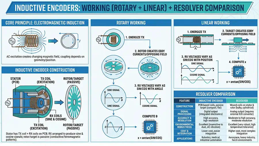
An infographic of the working principle of inductive encoders
Working Principle (Step-by-Step)
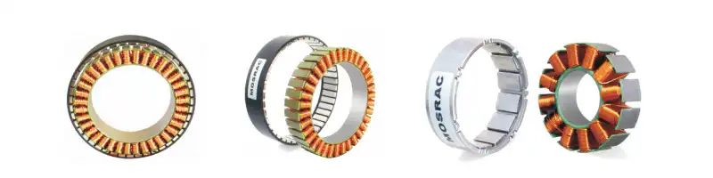
1. Rotor Movement - When the shaft rotates (or a linear target moves), a conductive rotor target moves relative to a fixed stator.
2. Stator Pattern Excitation - The stator contains patterned conductive tracks excited by an alternating current. This generates a localized electromagnetic field.
3. Eddy-Current Interaction - Once the rotor moves, it induces eddy currents in the conductive target. These currents alter the distribution of the electromagnetic field detected by the stator coils.
4. Signal Modulation - Changes in electromagnetic coupling modulate the amplitude and phase of the received signals. This encodes precise positional information.
5. Electrical Output Generation - The modulated signals are processed and converted into digital or analog outputs. They represent position, speed, or direction.
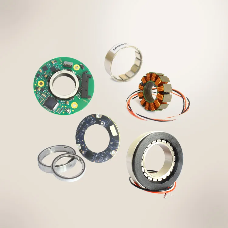
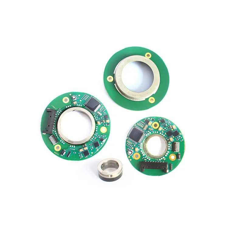
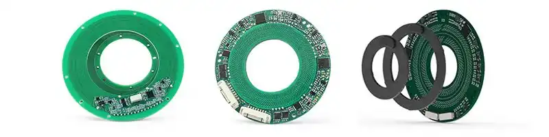
Core Encoder Building Blocks
1. Sensing Element - Electromagnetic coils embedded in the stator detect variations caused by rotor movement.
2. Signal Conversion Electronics - Analog front-end circuitry amplifies, filters, and demodulates raw signals into usable position data.
3. Digital Output Interface - Processed data is transmitted to the controller via interfaces such as SPI, SSI, BiSS-C, or CAN-based protocols.
Key Performance Terms
1. Resolution - The smallest detectable positional change, typically expressed in bits or counts per revolution.
2. Accuracy - The closeness of the measured position to the true mechanical position.
3. Latency - The time delay between mechanical motion and signal availability at the output.
4. Update Rate - The frequency at which position data is refreshed is critical for high-speed control loops.
This electromagnetic, non-contact working principle makes inductive encoders particularly valuable for engineers, designers, R&D teams, and students who require reliable, high-precision feedback in demanding environments.
Recommended Reading: Single-Turn vs. Multi-Turn Encoders: The Lean Guide
Types of Inductive Encoders
Inductive encoders can be classified in several ways depending on motion type, measurement method, range, mechanical integration, signal processing, and application requirements.
Inductive Encoders
This helps engineers select the most suitable encoder for their specific motion system.
1. By Motion Type
● Rotary Inductive Encoders: Measure the angular position or rotation of a shaft. Used in motors, robotic joints, rotary tables & automation axes requiring precise angular feedback.
● Linear Inductive Encoders: Measure linear displacement along a straight path. Used in linear actuators, positioning stages, and automation systems requiring non-contact linear feedback.
2. By Measurement Method
● Incremental Inductive Encoders: Generate position data as incremental changes relative to a reference point. Suitable for speed measurement and applications where absolute position recovery after power loss is not required.
● Absolute Inductive Encoders: Provide a unique position value for every mechanical position, enabling true position feedback immediately after power-up. Preferred for robotics, safety-relevant systems, and precision automation.
3. By Measurement Range
● Single-Turn Inductive Encoders: Measure angular position within one full revolution (0–360°). Common in compact systems and angle measurement applications.
● Multi-Turn Inductive Encoders: Track both angular position and the number of full rotations, making them ideal for articulated robots, servo presses, and lifting mechanisms.
4. By Mechanical Structure
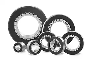
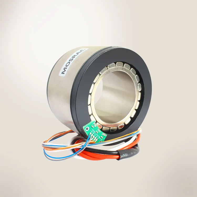
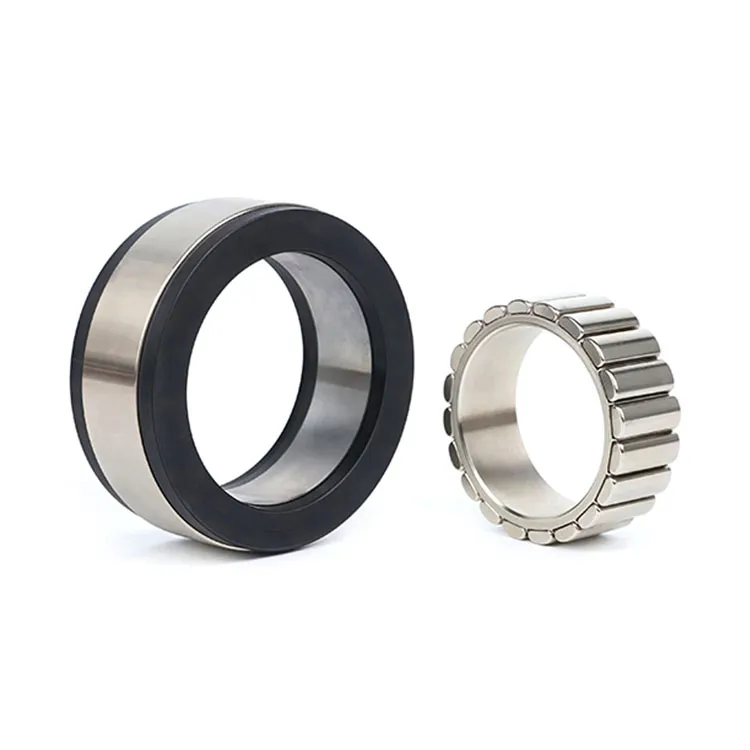
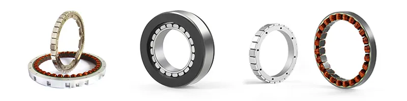
● Module Inductive Encoders (Packaged): Fully enclosed units designed for easy installation and protection against environmental exposure. Used where standard mounting and mechanical robustness are required.
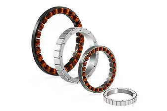
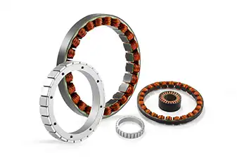
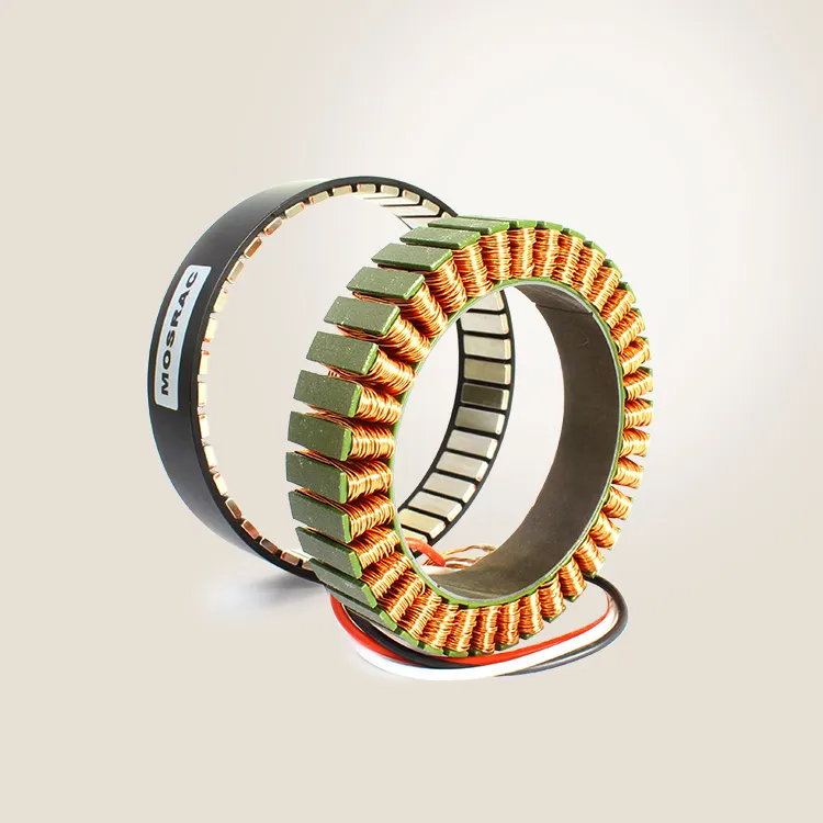
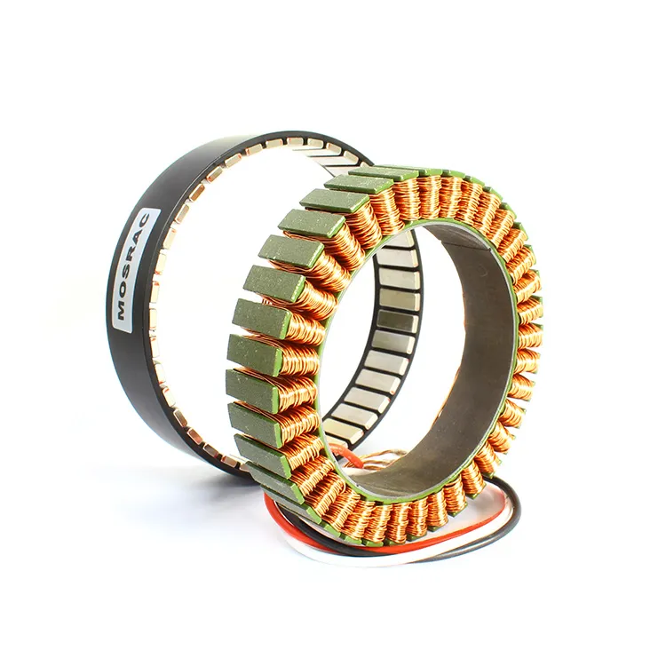
● Frameless / Kit Inductive Encoders (Unpackaged): Consist of separate stator and rotor components, allowing direct integration into motors or joints. These are ideal for robotics and frameless motor architectures where space and weight are critical.
5. By Signal Processing
● Analog Output Inductive Encoders: Provide continuous voltage or current outputs proportional to position. Used in simpler control systems and legacy automation.
● Digital Output Inductive Encoders: Transmit position data via digital interfaces such as SPI, SSI, or BiSS-C, offering high noise immunity and precise data transmission.
6. By Application
● High-Speed Inductive Encoders: Designed for fast rotational speeds and high update rates in dynamic motion systems.
● High-Resolution Inductive Encoders: Provide fine positional detail for precision robotics and automation.
● High-Temperature Inductive Encoders: Engineered to maintain accuracy under elevated thermal conditions.
Compact Inductive Encoders: Optimised for space-constrained designs such as robotic joints and embedded motor systems.
Recommended Reading: 14 Different Types of Encoders for Various Types of DC Motors
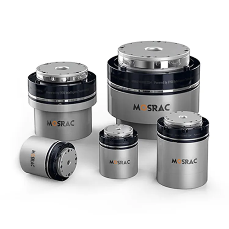
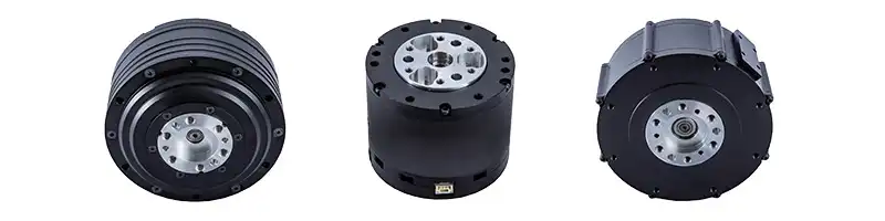
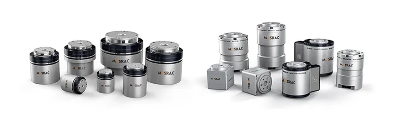
Mosrac Inductive Encoder Product Portfolio
Mosrac offers a specialized range of high-precision inductive encoders engineered for robotics, automation, and harsh industrial environments. Designed around non-contact electromagnetic sensing, these encoders deliver long-term reliability, compact integration, and deterministic feedback for demanding motion-control systems.
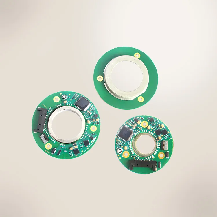
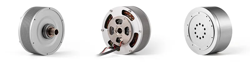
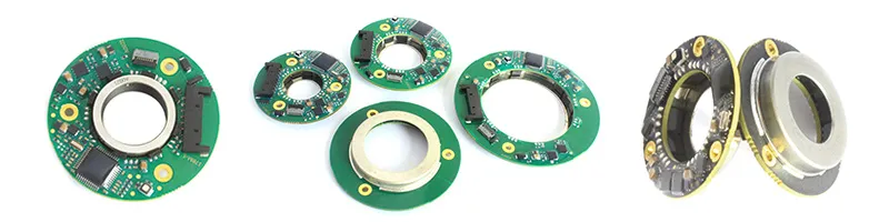
1. C-Series Inductive Rotary Encoders
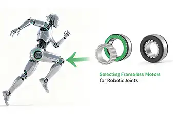
The C-Series is optimized for compact and lightweight robotic designs, where space, weight, and integration flexibility are critical. It can be seamlessly installed in robot joints or multi-axis automation equipment. The encoder is suitable for position feedback or improving commutation in frameless motors.
| Model | OD | ID | Thickness | Resolution | Accuracy |
| C0214 | 14.8 | 2 | 3.6 | 15~17 | ±0.03 |
| C0216 | 16.8 | 2 | 3.6 | 15~17 | ±0.025 |
| C0218 | 18.8 | 2 | 3.6 | 15~17 | ±0.02 |
| C0420 | 20 | 4 | 6.5 | 15~17 | ±0.05 |
| C1040 | 40 | 10 | 8.0 | 17~19 | ±0.015 |
| C1752 | 52 | 17 | 7.6 | 18~20 | ±0.01 |
| C2560 | 60 | 25 | 8 | 18~20 | ±0.008 |
| C3580 | 80 | 35 | 8 | 18~20 | ±0.008 |
| C48100 | 100 | 48 | 8 | 19~21 | ±0.006 |
| C70120 | 120 | 70 | 8 | 19~21 | ±0.006 |
| C90140 | 140 | 90 | 9 | 19~21 | ±0.006 |
| C120180 | 180 | 120 | 9 | 20~22 | ±0.003 |
| C172247 | 247 | 172 | 9 | 20~22 | ±0.003 |
Their salient features include:
● Ultra-thin, low-profile construction suitable for embedded motor and joint designs
● Large hollow shaft architecture, allowing cable routing or direct shaft integration
● Non-contact inductive sensing ensures zero mechanical wear and long operational life
● High repeatability and stable accuracy across temperature variations
● Ideal for robotic joints, cobots, and frameless motor assemblies requiring minimal mechanical stack-up
The non-contact absolute C-series encoder meets stringent industrial environment standards and offers a cost-effective, accurate, and reliable position sensing solution; customization options are available. They are well-suited for compact robotic joints where traditional optical encoders are too fragile or bulky.
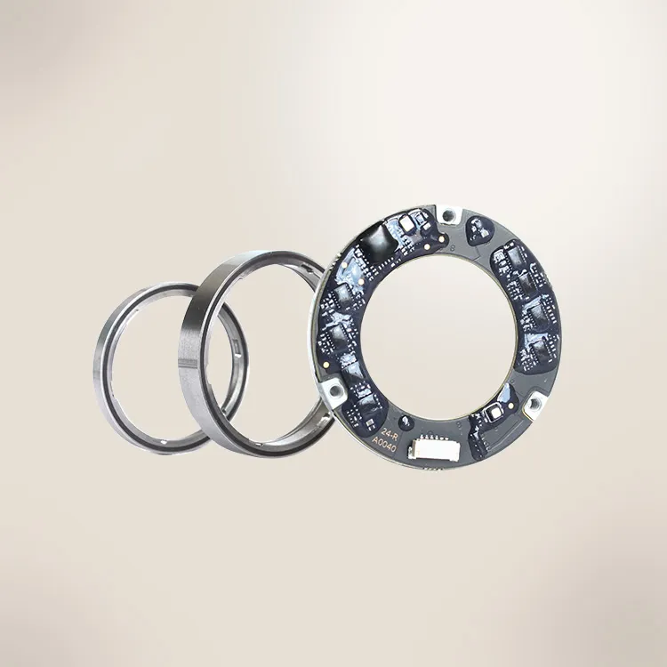
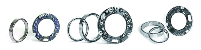
2. D-Series Inductive Rotary Encoders
The D-Series is designed for applications where functional safety and system redundancy are essential. The product includes three parts: a stator and two rotors. It is perfect for compact applications where space is tight and can be easily installed in robot joints or multi-axis automation systems.
The D-series encoder has two separate position-detection and signal-output systems, allowing for redundant operation and greatly increasing reliability.
| Model | OD | ID | Thickness | Resolution | Accuracy |
| D1034 | 34 | 10 | 7.6 | 17~19 | ±0.015 |
| D2050 | 50 | 20 | 7.6 | 17~19 | ±0.015 |
| D2158 | 58 | 18~21 | 7.6 | 18~20 | ±0.01 |
| D3670 | 70 | 36 | 7.6 | 18~20 | ±0.01 |
| D3178 | 78 | 31~35 | 7.6 | 18~20 | ±0.01 |
| D5690 | 90 | 56 | 7.6 | 19~21 | ±0.01 |
| D76110 | 110 | 76 | 7.6 | 19~21 | ±0.01 |
Their salient features include:
● Dual-system architecture with independent sensing channels
● Redundant position feedback increases fault tolerance and system reliability
● Deterministic output suitable for safety-relevant motion axes
● Robust performance in high-vibration and high-EMI environments
● Supports integration into advanced motion-control and safety systems
These characteristics make the D-Series suitable for industrial robots, automation axes, and machinery where uptime and safety compliance are critical.
3. DP-Series Inductive Rotary Encoders
The DP-series encoders consist of a single stator and an inner and outer dual rotor. It uses electromagnetic fields and recognition technology to implement a dual-encoder design on one side within an ultra-thin, narrow form factor.
The DB-Series combines dual-rotor sensing with an ultra-thin mechanical profile, delivering high performance in space-constrained applications.
| Model | OD | ID | Thickness | Resolution | Accuracy |
| DP1038 | 38 | 10 | 3.6 | 17~19 | ±0.015 |
| DP1646 | 46 | 16 | 3.6 | 17~19 | ±0.015 |
| DP2055 | 55 | 20 | 3.6 | 17~19 | ±0.015 |
| DP3065 | 65 | 30 | 3.6 | 18~20 | ±0.01 |
| DP3575 | 75 | 35 | 3.6 | 18~20 | ±0.01 |
| DP4585 | 85 | 45 | 3.6 | 18~20 | ±0.01 |
| DP55100 | 100 | 55 | 4 | 19~21 | ±0.01 |
| DP85130 | 130 | 85 | 4 | 19~21 | ±0.01 |
Their salient features include:
● Dual-rotor inductive design improves signal stability and accuracy
● Ultra-thin construction for tight installation envelopes
● High positional precision with low power consumption
● Excellent thermal stability and resistance to environmental contamination
● Ideal for space-constrained automation systems, compact drives, and integrated motor solutions
The DP dual encoder on one side features two independent detection and signal output systems, making it ideal for robot joints or multi-axis automation equipment with limited space.
Explore: Inductive Rotary Absolute Encoders
Inductive Encoder vs Optical vs Magnetic Encoders
Choosing the right encoder technology requires understanding the trade-offs between durability, signal integrity, accuracy, and long-term reliability.
Below is a practical engineering comparison of inductive, optical, and magnetic encoders based on real industrial operating conditions.
Environmental Durability Comparison
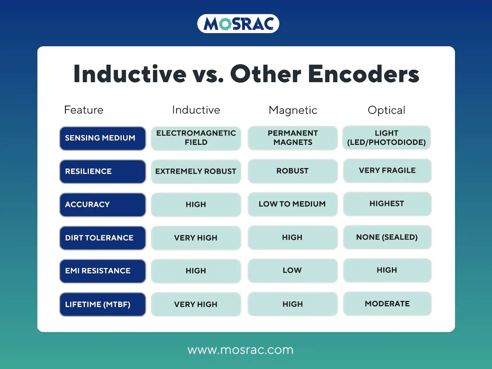
Inductive encoders are the most robust, operating reliably in environments with dust, oil, moisture, chemicals, and temperature extremes.
Optical encoders perform well only in clean, controlled environments; contamination directly degrades signal quality.
Magnetic encoders offer better durability than optical encoders, but can be affected by external magnetic fields and extreme temperatures.
EMI Resistance Differences
Inductive encoders provide excellent immunity to electromagnetic interference due to their differential electromagnetic sensing and signal processing.
Optical encoders are largely unaffected by EMI but suffer indirectly when contamination or vibration impacts optical alignment.
Magnetic encoders are more susceptible to EMI and stray magnetic fields, which can distort measurements in electrically noisy environments.
Maintenance and Lifetime Considerations
Inductive encoders require minimal maintenance and deliver long service life due to their non-contact, wear-free design.
Optical encoders often require periodic cleaning and maintenance, increasing downtime and lifecycle cost.
Magnetic encoders generally need low maintenance but may require recalibration or shielding in high-interference applications.
Accuracy vs Robustness Trade-Offs
Inductive encoders prioritize measurement stability and reliability, delivering consistent accuracy even under harsh mechanical and environmental stress.
Optical encoders typically offer the highest raw resolution and accuracy but sacrifice robustness.
Magnetic encoders balance accuracy and durability, making them suitable for many industrial applications.
Detailed Comparison Table: Inductive vs Optical vs Magnetic Encoders
Below is a technical comparison to help engineers evaluate encoder technologies based on real-world operating conditions:
Why This Matters for Engineers?
For robotics engineers, automation designers, and motion-control specialists, these advantages translate into higher system uptime, predictable control performance, lower total cost of ownership, and reduced field failures.
This is why industries are increasingly shifting from optical to inductive encoder technologies for next-generation motion systems.
Recommended Reading: Motor Encoders - Types, Features, Advantages, Applications, and Choosing the Right One
Key Advantages of Inductive Encoders
Inductive encoders are engineered for real-world industrial motion systems, where reliability, durability, and long-term accuracy matter more than ideal lab conditions.
Their non-contact, electromagnetic sensing principle gives them several decisive advantages over optical and mechanical alternatives.
1. No Optical Components (Contamination-Proof Operation)
Inductive encoders do not use LEDs, lenses, or code discs. As a result, they are unaffected by dust, oil, moisture, grease, or airborne particles. This makes them ideal for factories, mobile machinery, and outdoor environments where optical encoders frequently fail due to contamination.
2. Stable Accuracy Across Wide Temperature Ranges
Because inductive encoders rely on electromagnetic coupling rather than light or mechanical contact, their accuracy remains stable across temperature variations. They exhibit minimal thermal drift, ensuring consistent position feedback in applications exposed to heat, cold, or rapid temperature changes.
3. High Vibration and Shock Tolerance
Inductive encoders are inherently resistant to mechanical shock and vibration, as there are no fragile optical paths or contacting parts. This makes them well-suited for robotics, AGVs, heavy machinery, and aerospace-grade motion systems.
4. Long MTBF (Mean Time Between Failures)
With no physical wear mechanisms and high resistance to environmental stressors, inductive encoders offer a significantly higher MTBF than optical or potentiometric encoders. This directly improves system uptime and reduces lifecycle costs.
5. Minimal Maintenance Requirements
The non-contact design eliminates the need for periodic cleaning, recalibration, or replacement of consumable parts. Once installed, inductive encoders typically operate maintenance-free for the lifetime of the machine.
Common Industry Applications of Inductive Encoders
Inductive encoders are widely adopted across industries where reliability, environmental robustness, and long-term stability are more critical than operating in ideal conditions. Their non-contact electromagnetic sensing makes them especially suitable for demanding, real-world applications.
1. Robotics & Cobots
In robotics, inductive encoders are used for joint articulation and precise angular feedback, enabling smooth, controlled motion across multiple axes. Their compact, frameless configurations integrate directly into joints and frameless motor assemblies, supporting lightweight designs while maintaining accurate closed-loop control. This is particularly important for collaborative robots that require repeatability, compliance, and safety.
2. Industrial Automation
Automation systems in packaging, textile machinery, and heavy industrial equipment rely on inductive encoders for consistent position and speed feedback over long duty cycles. These environments often involve dust, fibers, vibration, and temperature variation; conditions in which inductive encoders maintain stable performance without frequent maintenance.
3. AGVs & AMRs
Automated Guided Vehicles (AGVs) and Autonomous Mobile Robots (AMRs) use inductive encoders for wheel position sensing, speed control, and motion feedback. Reliable encoder data ensures accurate navigation, smooth acceleration, and precise stopping, even in electrically noisy factory floors or logistics environments.
4. Aerospace & Defense
Aerospace and defense systems demand sensors that operate reliably under high vibration, shock, and wide temperature ranges. Inductive encoders are well-suited for actuators, positioning systems, and control surfaces where mechanical durability and signal stability are critical.
5. Harsh-Environment Motor Control
In industries such as steel manufacturing, mining, and outdoor automation, motors are exposed to extreme contamination, heat, and mechanical stress. Inductive encoders provide dependable position feedback in these harsh conditions, supporting continuous operation and reducing downtime in mission-critical motor control systems.
The inductive encoders enable robust motion control where traditional encoder technologies struggle, making them a key component in modern industrial and robotic systems.
How to Choose the Right Inductive Encoder?
Selecting the right inductive encoder is an engineering trade-off between control requirements, environmental exposure, interface compatibility, and mechanical integration. Use the checklist below to narrow options quickly and avoid under- or over-specifying your feedback system.
1) Define the Application Requirements
Start by identifying what the encoder must control and how it will be used:
● Robotics Joints / Cobots: high repeatability, smooth torque control, compact integration
● Motor Control (BLDC/servo): commutation feedback, low latency, stable speed/position sensing
● Automation Axes: consistent positioning under continuous duty cycles
● Mobile Robots (AGVs/AMRs): reliable wheel feedback and navigation stability
This determines whether your priority is fast dynamics, absolute position, or maximum reliability.
2) Evaluate Environmental Constraints
Inductive encoders are strong in harsh conditions, but you should still define the operating envelope:
● Contamination Exposure: dust, oil mist, moisture, washdown
● Mechanical Stress: vibration, shock, misalignment tolerance
● Electrical Noise: EMI from drives, inverters, and welding equipment
● Thermal Environment: continuous temperature, thermal cycling, localized motor heating
These factors affect housing selection, cable routing, shielding, and mounting strategy.
3) Set Required Resolution and Accuracy
Match feedback granularity to your control objectives:
● Resolution (counts/bit-depth equivalent) influences smoothness in low-speed control and positioning precision
● Accuracy governs how close the reported position is to the true mechanical position (critical in calibration-sensitive systems)
● For high-dynamic motion, don’t ignore latency and update rate, since slow feedback limits control-loop bandwidth
The practical approach is to define the minimum positional step, the maximum speed, and the allowable control error.
4) Choose the Right Interface
Confirm what your drive/controller supports and what your system architecture requires:
● SPI: compact, high-speed point-to-point communication
● SSI: simple serial interface, common in industrial systems
● BiSS-C: deterministic, high-speed, well-suited for precision motion control
● CANopen: useful when encoder data must live on a fieldbus network
Interface selection impacts wiring, EMC design, update rate, and system integration complexity.
5) Check Mechanical Integration Constraints
Inductive encoders are often selected specifically for integration flexibility—use that advantage:
● Frameless/Kit Designs: best for robotics joints and embedded motor feedback (minimal stack-up)
● Module/Packaged Encoders: faster installation, standardized mounting
● Shaft Type, hollow shaft needs, allowable airgap, and available axial space are key constraints
● Ensure the encoder form factor supports alignment tolerances and does not compromise bearing loads.
If you share your application (motor type, speed range, environment, interface, and space constraints), our engineering team at Mosrac can recommend the most suitable inductive encoder configuration — or design a custom solution for your robotics or automation system.
Conclusion
Inductive encoders are a key enabling technology in modern motion control, providing non-contact, reliable position feedback based on electromagnetic coupling and eddy-current sensing. Their ability to deliver stable, deterministic feedback makes them especially valuable in applications where environmental conditions and long operating cycles challenge traditional sensing methods.
Today, automation systems are moving beyond clean, controlled environments, so inductive encoders are increasingly replacing optical encoders. Superior resistance to contamination, vibration, temperature variation, and electromagnetic interference allows inductive solutions to maintain performance and reduce maintenance over the system’s lifetime.
Mosrac plays an important role in this transition by delivering precision-engineered inductive encoder solutions designed for robotics, automation, and harsh industrial environments. Explore the inductive encoder portfolio or request a custom-engineered solution to ensure reliable, long-term motion feedback for your next application.
Frequently Asked Questions (FAQs)
1. What is an inductive encoder?
A. The inductive encoder is a non-contact position sensor that uses electromagnetic coupling and eddy-current effects to convert rotary or linear motion into reliable electrical feedback signals.
2. How does an inductive encoder differ from an optical encoder?
A. Inductive encoders use electromagnetic sensing instead of light, making them resistant to dust, oil, vibration, and temperature changes, whereas optical encoders require clean, controlled environments.
3. Are inductive encoders suitable for robotics?
A. Yes. Inductive encoders are well-suited for robotics due to their compact form, vibration tolerance, and stable position feedback for robotic joints and frameless motor integrations.
4. Can inductive encoders be used with BLDC motors?
A. Inductive encoders are commonly used with BLDC motors to provide accurate rotor position feedback for commutation, torque control, and closed-loop speed and position regulation.
5. Why are inductive encoders ideal for harsh environments?
A. Their non-contact electromagnetic sensing is immune to contamination, EMI, shock, and temperature extremes, ensuring consistent performance and long service life in harsh industrial conditions.