Discover what a servo motor is, how it works, key components, control theory, and real-world applications. Learn how precision servo and torque motors deliver top performance.
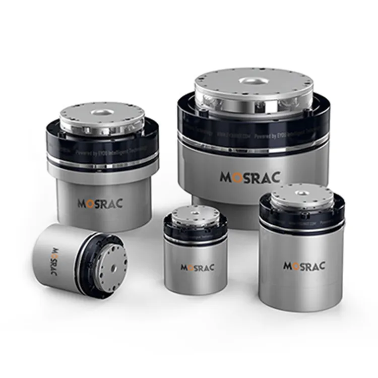
Frameless Servo Motor
Introduction
In today’s world of robotics, CNC machining, medical devices, and smart manufacturing, every movement needs to be precise, fast, and flawlessly repeatable. Yet traditional motors often fail to deliver this level of accuracy.
Once positioning drifts even slightly, production slows, energy is wasted, components wear out faster, and entire systems can fail. In high-stakes environments, like wafer-handling robots or surgical automation, such errors aren’t just inconvenient; they’re costly and dangerous.
This is where servo motors become essential! With closed-loop control, high torque density, and real-time feedback, they offer the accuracy and stability modern automation depends on. Mosrac delivers servo-ready frameless torque motors and magnetic absolute encoders designed for applications where performance cannot be compromised.
What Is a Servo Motor?
Basic Definition
The servo motor is a high-performance, closed-loop electromechanical actuator designed to deliver extremely precise position, speed, and torque control. Unlike standard motors that simply spin when voltage is applied, a servo motor continuously compares its actual motion to the commanded motion through a feedback system, usually an encoder.
This real-time correction allows servo motors to achieve sub-degree positioning, stable velocity control, and immediate torque response. These motors are indispensable in robotics, CNC machinery, medical devices, and semiconductor automation.
How Servo Motors Differ?
Servo motors stand apart because of their feedback-driven closed-loop architecture.
Here’s how they differ from common alternatives:
Servo Motor vs Stepper Motor
● The stepper motor operates in open-loop, meaning it moves without confirming whether it reached the intended position.
● It loses steps under high load and cannot provide real torque feedback.
● The servo motor, however, constantly monitors its motion using an encoder and adjusts dynamically, providing higher precision, efficiency, and speed.
Servo Motor vs Induction Motor
Induction motors are optimized for continuous rotation, stability, and power delivery, ideal for fans, pumps, and conveyors.
They lack precision control and cannot instantly correct position errors.
Servo motors excel in tasks requiring accurate angles, rapid acceleration/deceleration, or variable torque, areas where induction motors cannot compete.
Core Characteristics of Servo Motors
Servo motors are engineered for advanced automation due to several key attributes:
● High Torque Density: Optimized electromagnetic design delivers strong torque in compact frames, essential for robotics and multi-axis motion platforms.
● Closed-Loop Accuracy: Encoder feedback ensures millimeter-level or sub-degree precision even under varying loads.
● Fast Dynamic Response: Servo motors can accelerate, stop, and reverse almost instantly due to low rotor inertia and advanced control algorithms.
● Low Noise & High Efficiency: Brushless designs and optimized commutation minimize electrical and acoustic noise while maintaining excellent power efficiency.
● Long Operational Life: With no brushes to wear out and advanced thermal management, servo motors offer years of consistent performance in demanding industrial environments.
The well-designed servo system delivers not just movement, but controlled, intelligent, and repeatable motion, making it the backbone of modern high-precision engineering.
Recommended Reading: Frameless Motor vs Servo Motor: What's Best for Your Design?
How Does a Servo Motor Work? (Complete Working Principle)
The servo motor operates on the foundation of closed-loop control, a system in which every movement is continuously monitored, compared, and corrected. This is what allows a servo to achieve the ultra-precise positioning, repeatability, and responsiveness required in high-end automation.
Closed-Loop Control: The Foundation
A servo system works by continuously cycling through this sequence:
Command Signal → Controller → Amplifier/Drive → Servo Motor → Feedback Device → Controller
1. The controller sends a target position, speed, or torque command.
2. The drive converts this command into the appropriate motor current.
3. The motor produces torque and moves the load.
4. The encoder immediately reports the actual position back to the controller.
5. If there is any error between the command and actual movement, the controller compensates in real time.
This loop runs thousands of times per second, enabling stable, high-accuracy motion—even under unpredictable loads.
Recommended Reading: Single-turn vs. Multi-turn Encoders: The Lean Guide
Essential Control Concepts in Servo Systems
PID Control
The heart of servo performance is PID (Proportional–Integral–Derivative) control.
● P - reacts to the present error
● I - removes long-term offset
● D - stabilizes rapid changes
Proper PID tuning ensures a servo stops precisely at the target point without overshoot, vibration, or hunting.
Velocity Loop
Regulates how fast the motor turns. Critical for applications like conveyors, robotic joints, and CNC machining.
Position Loop
Ensures the motor reaches the exact angular or linear position commanded — often to sub-degree accuracy.
Torque Loop
Controls motor current, which directly translates to torque. This loop responds in microseconds and is essential for force control, load balancing, and handling sudden disturbances.
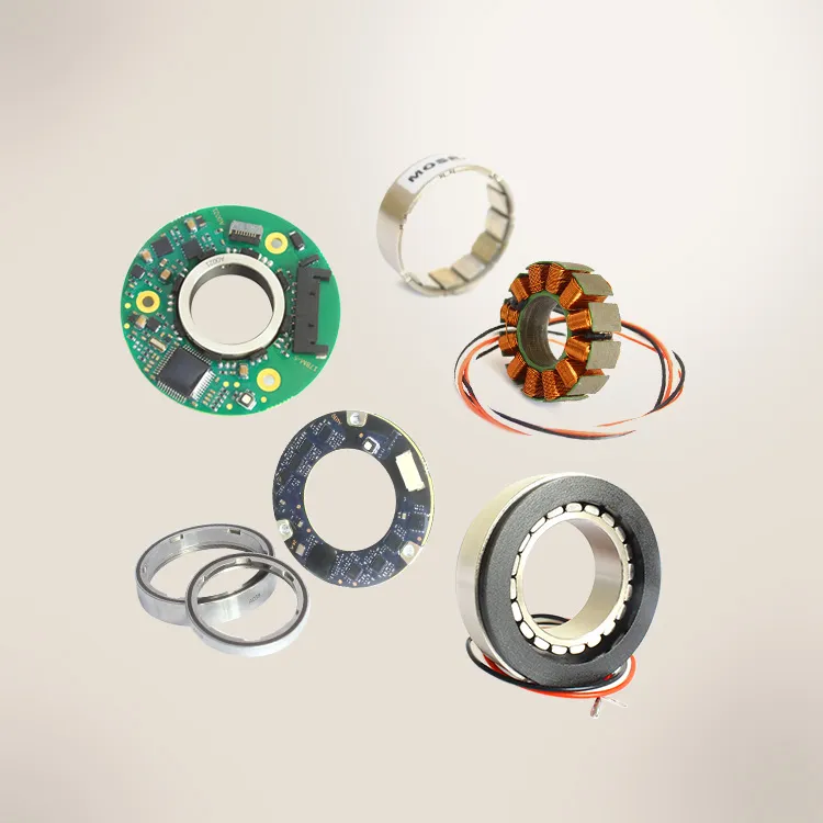
Key Components of a Servo System
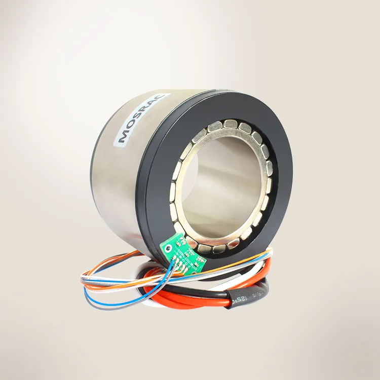
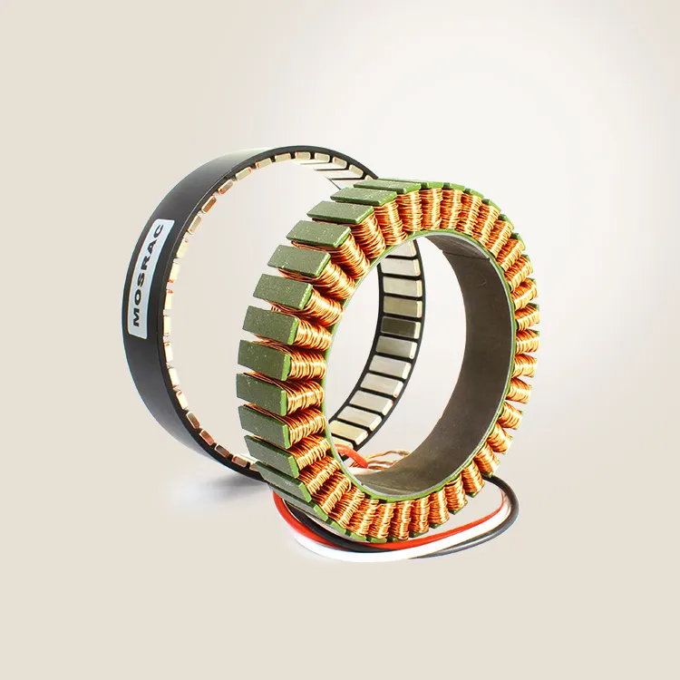
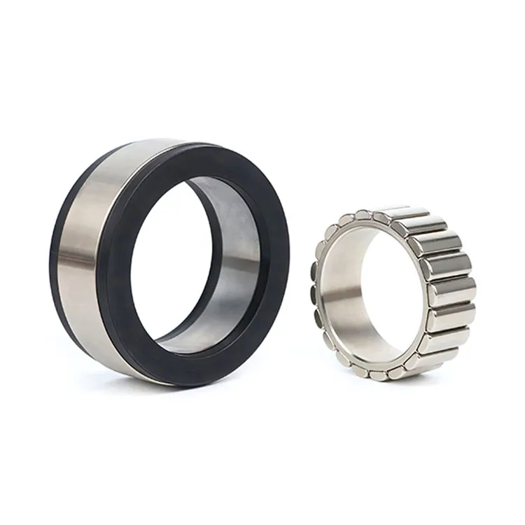
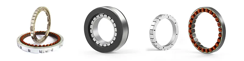
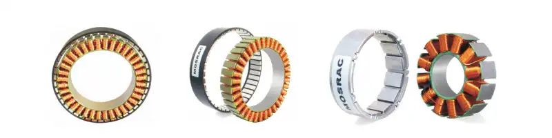
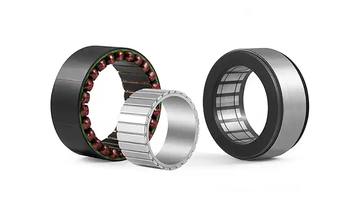
1. Servo Motor (Rotor–Stator Structure)
The internal structure of a servo motor is optimized for precision and high torque density:
● Permanent-Magnet Rotor: High-strength rare-earth magnets (typically NdFeB) create strong, stable magnetic fields for fast acceleration and accurate torque output.
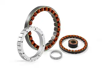
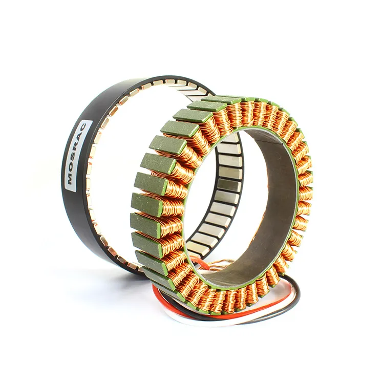
● Stator Windings: Multi-phase windings (usually 3-phase) generate rotating electromagnetic fields that interact with the rotor to produce controlled motion.
● Torque Generation: Torque is proportional to the motor current, making servo motors ideal for real-time current control loops.
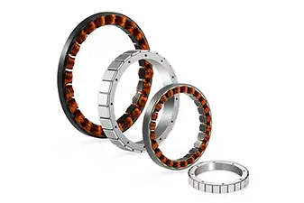
Mosrac’s high-precision torque motors are engineered for servo applications requiring ultra-smooth rotation, high torque density, and zero-backlash performance.
2. Servo Drive / Controller
The servo drive is the brain behind the motion. It:
● Receives command signals (position, velocity, torque)
● Performs PID calculations thousands of times per second
● Converts digital commands into PWM (Pulse Width Modulation) or current output
● Ensures accurate phase commutation for smooth motor rotation
Modern servo drives also support industrial communication protocols like EtherCAT, CANopen, and RS-485 for synchronized multi-axis motion.
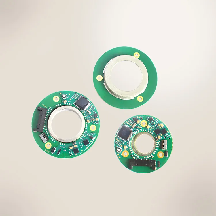
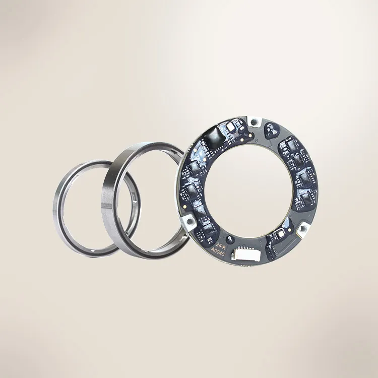
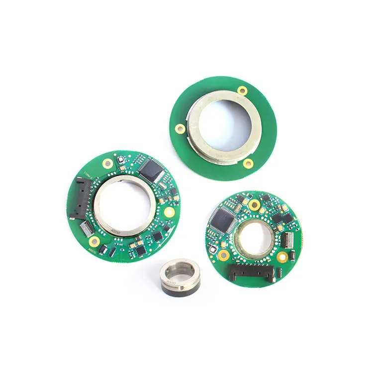
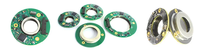
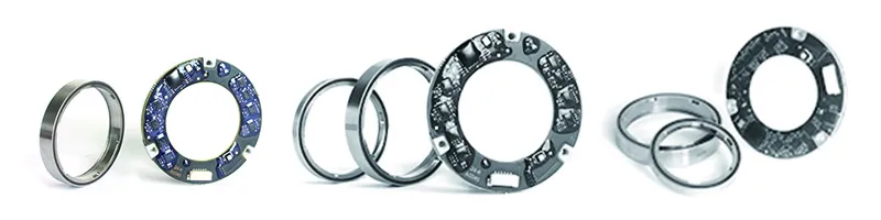
3. Feedback Device (Encoder / Resolver)
Feedback is what makes a servo “smart.”
● Incremental Encoders: Provide pulse-based feedback and high resolution
● Absolute Encoders: Provide unique position values at every angle, no homing required
● Resolvers: Robust analogue feedback suitable for harsh environments
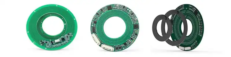
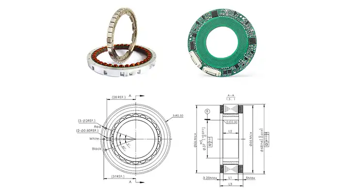
The magnetic absolute encoders offer high resolution, excellent repeatability, immunity to dust, oil, and vibration, compact size for robotics and medical devices. Those engineered at Mosrac’s Shenzhen-based facility ensure error-free, high-resolution feedback crucial for servo loop accuracy, enabling stable and precise control in demanding applications.
4. Power Supply and Amplifier
The servo system requires stable and efficient power delivery:
● AC/DC Power Supply: Must match the voltage and current requirements of the motor and drive
● Current Amplifier: Regulates current in the torque loop, ensuring instant torque response
● Thermal Considerations: Proper cooling, PCB layout, and power derating ensure long-term reliability
Power architecture directly affects servo smoothness, torque availability, and system efficiency.
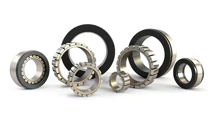
Types of Servo Motors
Servo motors come in multiple configurations depending on the application, desired precision, torque requirements, and control architecture.
1. AC Servo Motors
AC servo motors are the most widely used in industrial automation due to their high torque density, excellent efficiency, and robust high-speed performance. They rely on three-phase AC input and advanced field-oriented control to deliver precise torque and smooth motion.
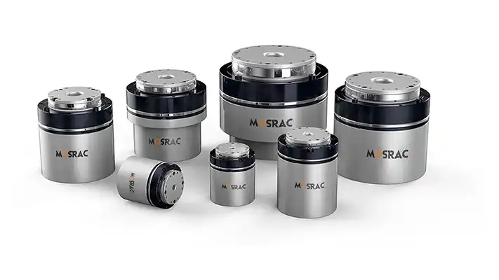
U130 Series Servo Motors; Specs: 419-755 W | 5.00-18.00 Nm | 400-1400 rpm | 48 VDC or 220 VAC
The technical advantages include a superior torque-to-weight ratio, high rotational speeds (ideal for CNC spindles, robotics, automated packaging), excellent thermal characteristics due to sinusoidal commutation, and suitability for continuous-duty cycles. U130 Series Frameless Servo Motors excels in these environments, offering the perfect blend of performance and reliability.
They are useful in robotics, CNC machines, industrial arms, semiconductor equipment, and pick-and-place automation.
2. DC Servo Motors
DC servo motors are simpler in construction and operation, but are less efficient than their AC counterparts. They use brushed or brushless DC control systems and provide fast response at low speeds.
The technical advantages include high starting torque, simple speed control via voltage variation, limited by brush wear (in brushed types), and lower efficiency and a shorter lifespan compared to AC servos.
They’re best suited for small-scale motion control, educational kits, hobby robotics, and lightweight automation.
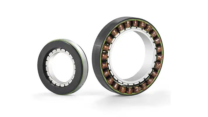
3. Brushless Servo Motors (BLDC Servos)
Brushless servo motors combine the advantages of servo feedback with the durability and efficiency of a brushless design. They use electronic commutation for smooth and accurate rotation.
The key characteristics include very high efficiency, zero brush wear, which extends lifespan, low acoustic & electrical noise, and precise torque and velocity control.
The ideal applications include surgical robots, collaborative robots, drones, high-performance actuators, and precision medical automation.
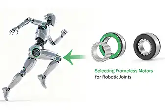
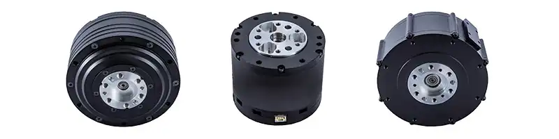
The frameless BLDC servo motors by Mosrac are engineered for robotics, cobots, and surgical automation, where precision, torque density, and smooth operation are non-negotiable. These motors integrate seamlessly into compact assemblies, enabling lightweight yet powerful motion systems.
4. Linear Servo Motors
Linear servo motors convert electrical energy directly into linear motion without requiring rotary-to-linear conversion mechanisms like lead screws or belts.
The technical advantages include native linear actuation, zero backlash, ultra-high positioning resolution, silent, and smooth linear acceleration.
The common uses include semiconductor wafer-handling stages, 3D metrology systems, medical imaging tables, and high-end motion platforms.
Recommended Reading: Torque Motor vs Servo Motor: Key Differences, Applications, and Benefits
Detailed Working Principle of a Servo Motor
The servo motor doesn't simply rotate — it thinks, corrects, and adjusts thousands of times per second. This intelligent behavior is enabled by a tightly integrated cascade of control loops and feedback mechanisms.
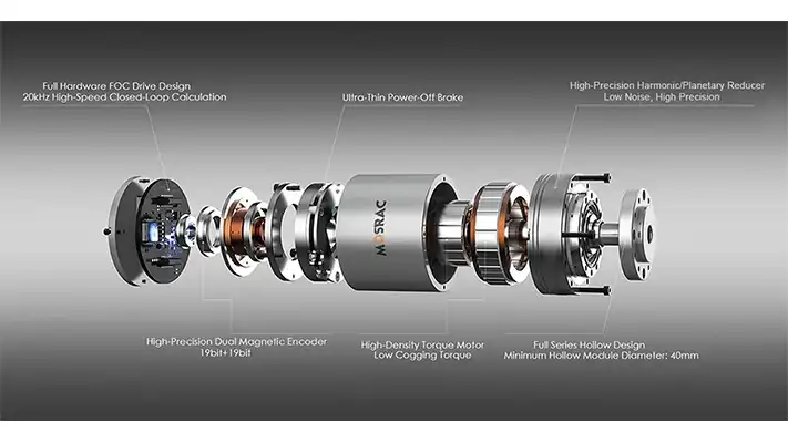
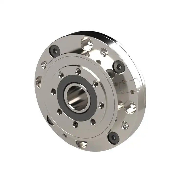
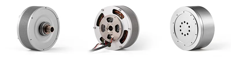
Detailed Overview of an Integrated Servo Robot Joint Module
Below is the complete working principle broken down into five critical steps:
Step 1 – Receiving the Command Signal
The servo system starts by receiving a command from the controller or PLC. This command specifies:
● Target Position (e.g., rotate to 37.5°)
● Target Velocity (e.g., move at 1200 RPM)
● Target Torque/Force (e.g., apply 0.8 Nm)
The common communication methods include:
● PWM (Pulse Width Modulation): Used in compact embedded applications
● Analog Voltage (0–10V or ±10V): Smooth speed/position control
● CANopen: Popular in robotics and distributed control
● EtherCAT: High-speed industrial networking with microsecond-level synchronization
Once received, the controller interprets the command and prepares the control loops.
Step 2 – Error Detection
Once the motor begins to move, the encoder or resolver continuously measures the actual position, speed, and direction of rotation. This feedback is sent to the controller instantly. The controller compares:
Commanded Value – Actual Value = Error
This “error signal” is the basis for all servo corrections. Even a tiny deviation (e.g., 0.01°) triggers immediate compensatory action, allowing servo motors to achieve extremely tight tolerances.
Step 3 – PID Compensation
After detecting an error, the servo controller applies PID algorithms to correct it most efficiently and stably.
●● P — Proportional Term corrects present error.
Higher P = faster response, but too high → overshoot or vibration.
●● I — Integral Term removes accumulated error over time.
Essential for applications requiring zero steady-state error.
●● D — Derivative Term predicts future error based on the rate of change.
Helps stabilize rapid motion, reduce overshoot, and prevent oscillation.
Properly tuned PID ensures smooth movement, high stability, fast settling time and no hunting or jitter. This is the mathematical heart of servo accuracy!
Step 4 – Motor Actuation
Once the PID correction is computed, the servo drive translates it into actionable power:
● Converts control signals into three-phase current
● Determines the exact magnetic vector for motor rotation
● Applies the required current proportional to the torque demand
Because torque in a servo motor is directly proportional to current, even tiny current adjustments create extremely fine torque changes.
The result is an instant torque response, enabling rapid acceleration, precise deceleration, and repeatable micro-movements. High-end servo drives also ensure smooth commutation, low electrical noise, and efficient energy usage.
Step 5 – Continuous Feedback Loop
The entire process: measure → compare → correct → actuate, repeats thousands of times per second (often at 4–16 kHz loop frequency).
This continuous loop ensures:
● Real-time correction to achieve the exact position
● Stable velocity under varying load
● Consistent torque output even with disturbances
● Zero drift during long operating cycles
If the load suddenly changes (e.g., a robot arm picks up a weight), the servo instantly compensates to maintain performance.
Servo Motor Specifications You Must Know
Selecting the right servo motor requires understanding a few critical engineering specifications. Below are the four most important servo motor specifications every engineer must evaluate.
1. Torque Constant (Kt) & Speed Constant (Ke)
The torque constant (Kt), measured in Nm/A, defines how much torque a motor produces per ampere of phase current. The higher Kt means more torque for the same current. This helps reduce thermal load and improve system efficiency.
The speed constant (Ke), measured in V/kRPM, defines the back-electromotive force (back-EMF) generated per unit speed. The higher Ke means more voltage is required to achieve high speed.
In most brushless servo motors: Kt ≈ Ke (in SI units)
This means torque production and EMF generation are tightly linked. A motor designed for high torque density usually has a higher Kt and lower base speed, while a motor designed for high speed has a lower Kt.
2. Torque–Speed Curve
Every servo motor has a characteristic torque–speed curve that defines how torque changes as the motor’s speed increases.
Continuous Torque: The maximum torque the motor can deliver indefinitely without overheating. It is used for steady-state or repetitive operations.
Peak Torque: The higher torque level available for short-duration bursts, typically a few seconds. It is used for acceleration, overcoming static friction, or lifting loads.
Thermal Limits: The ability of a motor to sustain torque is limited by heat buildup in stator windings, power electronics, and magnets (risk of demagnetization).
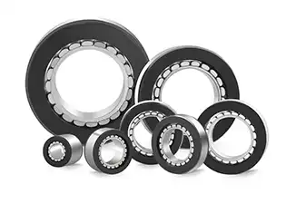
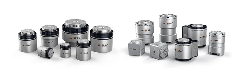
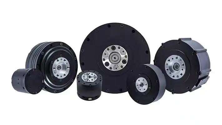
Frameless Torque Motors - Mosrac
Proper thermal dissipation, often optimized in frameless torque motors, ensures stable performance in long-duty applications.
3. Encoder Resolution
Encoder resolution determines how finely a servo system can measure position. It is one of the key factors behind motion smoothness, velocity stability, precision positioning, and repeatability.
The high-resolution encoders (17–22 bits) enable micro-level control, essential for 6-axis robot arms, surgical automation, semiconductor lithography, and high-performance gimbals.
Magnetic absolute encoders at Mosrac provide high-resolution, error-free feedback even in vibration-heavy or dusty environments, ensuring servo loops remain stable and accurate. This level of feedback quality is critical for advanced motion control.
4. Inertia Matching
Inertia matching is often overlooked — yet it is one of the most important factors in servo tuning and performance. The load inertia should be within a recommended ratio of the motor’s rotor inertia (typically 3:1 to 10:1, depending on the drive).
If the load inertia is too high, the servo will overshoot, there may be increased oscillation, PID tuning will become harder, resonance and vibration will increase, and the motor will work harder, ultimately causing overheating.
If matched correctly, you’ll experience a smoother acceleration, fast settling time, higher precision, and longer motor lifespan.
Designers must choose a motor with sufficient rotor inertia or compensate with gear reduction. The frameless motors manufactured are ideal here… Their high torque density allows engineers to place the motor inside the joint with minimal weight, dramatically improving inertia balance and dynamic response.
Servo Motor Control Techniques
Modern servo systems rely on advanced control strategies to achieve smooth, stable, and highly accurate motion. Below are the key control techniques that shape how servo motors behave in real-world applications.
PID Control
PID control remains the backbone of servo motion. It continuously compares the commanded value with the actual motion and applies corrective action using proportional, integral, and derivative responses. When tuned well, PID ensures that the motor accelerates quickly, stops exactly where it should, and avoids oscillations or overshoot. In pick-and-place robots, medical actuators, or CNC tool heads, this balance between speed and stability is essential. Although PID is decades old, its reliability and predictability keep it at the heart of nearly all servo drives today.
Field-Oriented Control (FOC)
FOC takes servo performance a step further by regulating current to maximise torque efficiency. Instead of controlling each motor phase independently, FOC transforms them into orthogonal components—one for generating torque and the other for field alignment. This allows the motor to react faster, operate cooler, and maintain smooth torque even at low speeds. For high-precision applications like semiconductor equipment or automated inspection systems, FOC provides the kind of quiet, vibration-free motion that standard control methods cannot match.
AI-Based Control Optimization
AI is emerging as a powerful tool for motion refinement! Instead of relying solely on mathematical tuning, machine learning algorithms can analyze vibration patterns, overshoot tendencies, and thermal characteristics to predict faults before they occur. AI-driven adaptive control adjusts PID parameters in real time, improving stability under dynamic loads—like when a collaborative robot arm lifts an object slightly heavier than expected. This level of intelligence enables smoother motion, reduced wear, and better long-term performance without the need for constant manual retuning.
Real-World Applications of Servo Motors
Servo motors power the backbone of modern automation. Their ability to deliver fast, accurate, and repeatable motion makes them indispensable across industries where precision directly impacts productivity, safety, and product quality. Below are the most influential sectors where servo technology is reshaping performance standards
1. Industrial Automation
In automated production lines, servo motors are the driving force behind conveyors, pick-and-place units, packaging machines, and high-speed assembly systems. Here, cycle time is everything. Faster acceleration, shorter settling times, and stable torque under load directly translate to higher throughput. The high-torque frameless motors allow system designers to reduce mechanical inertia and improve responsiveness, resulting in smoother movements and shorter production cycles — an immediate upgrade in industries where efficiency defines competitiveness.
2. Robotics & Cobots
Robotic joints demand motion that is smooth, quiet, and repeatable, including the ability to hold position with minimal energy consumption. The closed-loop design of the servo motor ensures each joint moves precisely to the commanded angle, even when external forces or payload variations occur. Cobots go further, requiring torque sensitivity for safe human interaction. The frameless motors paired with magnetic absolute encoders offer zero-backlash servo behavior with high-resolution feedback, enabling lightweight, agile robot arms with exceptional accuracy in every degree of freedom.
3. CNC Machines / Machine Tools
CNC machining is built on rigidity, precision, and micro-level repeatability. Servo motors control tool heads and linear stages that must reach exact coordinates at high speed without vibration. High-resolution feedback ensures stable feed rates, while fast dynamic response allows rapid tool changes and reduced settling time between cuts. This combination improves machining accuracy, lowers scrap rates, and supports advanced manufacturing techniques such as micro-milling and multi-axis machining.
4. Aerospace & Defence
From UAV gimbal stabilization to aircraft control surfaces, servo motors are essential wherever motion must be controlled with absolute reliability. In drone gimbals, they counteract vibration and turbulence in milliseconds to keep cameras stable at altitude. In defense systems, servos operate targeting mechanisms, rotors, and actuators where precision is mission-critical. These environments demand motors that are lightweight yet capable of delivering high torque — attributes found in modern frameless servo designs.
5. Medical Devices
The medical field requires motion systems that are quiet, clean, and extremely precise. Servo motors enable smooth, controlled movement in surgical robots, imaging equipment, infusion pumps, and prosthetic limbs. Their ability to deliver force feedback and micro-level positioning makes them ideal for minimally invasive surgery systems where the smallest error can have major consequences. High-resolution encoders ensure consistent performance even during prolonged procedures.
6. Semiconductor Manufacturing
Semiconductor fabrication pushes motion control to its absolute limits. Wafer-handling robots must move delicately and predictably without vibration or particulate contamination. Lithography and inspection stages require nanometer-level precision, making servo-driven direct-drive systems the preferred choice. The frameless torque motors eliminate mechanical transmissions, reducing backlash and improving long-term accuracy. Combined with high-bit encoders, these systems offer the stability required for next-generation chip manufacturing.
How to Select the Right Servo Motor?
Choosing the correct servo motor is not just about selecting power or speed. It’s about finding the perfect match between load dynamics, application requirements, and control precision.
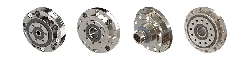
Integrated Servo Robot Joint Module
Planetary Integrated Robot Joint Module
Step-by-step Motor Selection Checklist
1. Define the Load Requirements
Start by calculating the load the motor must move or hold. This includes static loads, dynamic loads, frictional forces, and gravitational effects (for vertical applications). Understanding the load profile ensures the motor delivers adequate continuous and peak torque.
2. Determine Torque & Speed Requirements
Every motion profile has a unique torque–speed envelope.
● Continuous torque is needed for steady operation.
● Peak torque handles acceleration, sudden load changes, and starting inertia. Matching these with the torque–speed curve of the servo motor ensures the motor operates within its safe, efficient range.
3. Specify Accuracy & Resolution Needs
Applications like robotics, semiconductor stages, and medical devices require extremely fine positioning. This means selecting high-resolution encoders, low-cogging motors, and drives capable of high loop frequencies.
4. Consider Continuous vs Peak Duty Cycles
A servo operating close to peak torque for long periods will overheat. Thermal derating, motor insulation class, and cooling methods must be factored in. Frameless torque motors excel here due to efficient electromagnetic design and improved thermal pathways.
5. Evaluate the Environmental Conditions
Temperature, humidity, dust, vibration, and required IP protection influence motor selection. Semiconductor and medical systems often need low particulate, low-noise motors, while outdoor applications require a rugged design.
6. Check Encoder Resolution & Feedback Type
Encoder performance directly affects motion stability. Absolute encoders eliminate the need for homing, while high-resolution bits improve control loops and reduce jitter.
7. Review Mechanical Integration
Consider the motor’s form factor:
● Frameless Motors for compact or lightweight designs
● Housed Servo Motors for plug-and-play integration
● Direct-Drive Configurations for zero-backlash systems
Mosrac offers all of the above-mentioned motors, offering engineers flexibility without compromising torque density.
Application-Based Motor Sizing Example
Let’s consider a simplified example of sizing a motor for a robotic joint:
1. Required Torque:
Calculate torque using τ = F × r + inertia components from link mass.
2. Load Inertia:
Robot arms increase inertia exponentially with distance. Matching this with motor rotor inertia ensures stable performance.
3. Gear Ratio:
High-ratio gear systems reduce load inertia seen by the motor but may introduce backlash. Direct-drive systems (like Mosrac DDR motors) eliminate this.
4. Encoder Resolution:
Joint precision depends on encoder bit depth. More bits → finer angular steps → smoother motion.
With custom engineering support by Mosrac, these parameters can be optimized to create a perfectly balanced and highly responsive servo-driven system.
Common Servo Motor Disadvantages & Troubleshooting
Below are the key problems you may encounter and how to solve them effectively.
Overheating
Overheating is one of the most frequent servo-related issues. It typically appears during high-duty cycles, continuous high torque demand, or poor thermal management. Excessive temperature shortens motor lifespan and can lead to insulation breakdown.
Troubleshooting Tips:
● Verify that the PWM frequency is correctly configured for the drive and motor combination.
● Check the current limit settings — overdriving the motor rapidly increases heat.
● Reduce excessive mechanical load or friction that forces the motor to work harder.
● Ensure proper ventilation and consider improving heat dissipation in enclosed systems.
Oscillation / Hunting
Oscillation occurs when the servo motor repeatedly overshoots and corrects its position, creating instability or jitter. This is especially noticeable in robotic joints, precision stages, and inspection systems.
Common Causes:
● Incorrect or overly aggressive PID tuning
● Low-resolution or noisy encoder feedback
● Inertia mismatch between load and motor
● Latency or noise in the control loop
Troubleshooting Tips:
● Re-tune PID parameters, starting with the proportional gain.
● Increase encoder resolution or switch to absolute encoders for cleaner feedback.
● Evaluate the load inertia and adjust mechanically or through drive settings.
Torque Ripple
Torque ripple is the uneven torque output that causes small, periodic disturbances in rotation. While often subtle, it can significantly affect applications requiring ultra-smooth motion, such as wafer handling, optical alignment, or high-end robotics.
Common Causes:
● Poor commutation accuracy
● Low-grade motors with uneven magnetic fields
● Incorrect motor parameter settings in the drive
Troubleshooting Tips:
Improve commutation by ensuring accurate electrical angle detection.
Use high-quality motors with optimized magnet placement and winding symmetry.
Reconfigure motor constants (Ke, Kt, pole pairs) in the drive if mismatches exist.
Noise / Vibration
Mechanical noise or vibration typically indicates deeper issues such as system imbalance, misalignment, or control-loop instability. Left unchecked, it leads to premature wear and reduced precision.
Common Causes:
● Inertia mismatch between motor and load
● Improper shaft coupling or mechanical misalignment
● Feedback errors from loose or damaged encoder wiring
● Excessive velocity gain or aggressive acceleration profiles
Troubleshooting Tips:
● Ensure that load inertia is within the drive’s recommended ratio for stable control.
● Inspect couplings, bearings, and mounts for alignment problems.
● Check encoder cabling and grounding for noise or signal integrity issues.
● Adjust acceleration/jerk limits for smoother profiles.
Explore More: Integrated Servo Robot Joint Module | PDF | 3D
Conclusion / CTA: Get Help With Your Application
Servo motors have become essential to modern automation, delivering the precision, speed, and reliability that advanced robotics, CNC machines, medical systems, and semiconductor tools demand. Their closed-loop architecture, high torque density, and rapid response make them the preferred choice wherever controlled motion directly impacts performance and quality.
For engineers designing high-accuracy systems, the right motor and encoder combination can dramatically improve cycle time, stability, and long-term reliability. This is where Mosrac stands out — offering servo-ready frameless torque motors and high-resolution magnetic absolute encoders built for demanding applications.
Contact Mosrac Today for tailored motor selection support, or request a quotation directly from our product catalog!
Frequently Asked Questions (FAQs)
1. What are the core components of a servo motor?
The complete servo system includes a motor, drive/controller, encoder or resolver for feedback, and a power supply. Together, these elements enable closed-loop precision and stable motion control.
2. What are the main advantages of using a servo motor?
Servo motors offer high accuracy, fast dynamic response, excellent torque control, and efficient closed-loop operation — making them ideal for robotics, CNC machines, and high-performance automation.
3. What should engineers look for when selecting a servo motor?
Evaluate torque and speed requirements, encoder resolution, inertia matching, thermal performance, and integration needs. These factors ensure smooth, reliable motion under real-world loads.
4. How does a servo motor differ from a stepper or induction motor?
Steppers operate open-loop with lower accuracy, while induction motors suit constant-speed tasks. Servos provide closed-loop precision, superior torque performance, and smoother control across all speeds.
5. Why is encoder resolution so important in servo systems?
High-resolution encoders improve positioning accuracy, velocity stability, and control-loop performance. They’re essential for robotics, medical devices, and semiconductor stages where precision is critical.
6. Can servo motors run continuously?
Yes — servo motors can operate continuously as long as thermal limits are respected. Proper cooling and correct torque sizing ensure long-term, stable performance.